A PCB breadboard is a sort of prototype board. Unlike a printed circuit board, which requires permanent solder connections, breadboards include sockets to which electrical components can be connected.
A PCB breadboard is ideal for prototyping small and large-scale electronic projects, and they are utilized for a wide range of systems, from simple digital and analog circuits to entire CPUs. So, before you need a permanent circuit board, you may need to do some basic work on an appropriate breadboard.
The breadboard’s nature as a temporary device for testing circuit connections rather than a permanent circuit board allows it to easily change the connected electronic devices during testing while still achieving its layout objectives. can do.
When beginning an electrical project, board designers must be able to determine the main types of boards that will be best suited for the project in question from the start. Regular printed circuit boards are more suited for a wide range of tasks, but breadboards are better suited for custom projects.
What Does the Term ”Breadboard” Mean?
The term ”breadboard” has its origin in the history and invention of electronic devices. Back in time, with the advent of circuit boards, engineers would fix sockets to wooden boards as they worked, and the wood they would mostly use was the same wood they used in cutting bread.
As the tradition passed down through time, the term ”breadboard” stuck and is now commonly used within the scope of electrical engineering.
How Does a PCB BreadboardWork?
- Typically, you can create a solderless breadboard layout before creating permanent PCB boards or the actual electronic device, because components on a breadboard can be removed or replaced. Wire connections would be made following drawn schematics.
- The prototype area, which consists of two rows of five holes, is located in the board’s center. In the channel that runs between the two rows, a chip with pins on both sides is placed to prevent connections between them.
- Power buses for grounding and operating electricity are located on the breadboard’s side.
- Integrated circuits are suitable for breadboards. You can access the pins on either side of the present chip by placing IC chips over the channel.
- Then, to finish the circuit, you connect an LED from the channel to the ground bus and a resistor to the power bus through the channel.
Parts of a Breadboard
Below are the parts that you should know about so that you can better operate one if you ever need to use it.
Terminal Strips
Conducting terminal strips are located inside each breadboard. Each socket and strip are separated by approximately 2.54mm. These strips allow a component leg or wire is inserted into a breadboard’s exposed holes, securing it firmly.
When you insert that component, it will be connected electrically to everything else in that row. Because the rows of metal have conductive properties, current can flow through freely.
Each row stands alone, distinguished by a dividing crevasse that sits amidst the breadboard. This divide separates both sides of each row such that they are not connected together. This distance allows for approximately five points of connection on both sides of the divide.

Power Rails
Power rails are typically found along each side of the breadboard. They are metallic in nature and they look a lot like the horizontal terminal strips, except that the terminal strips are all connected.
The rails provide easy power access wherever it is needed within the circuit. To indicate the positive and negative sides, they are usually labeled with the “+” and “-” signs and have red, blue, or black stripes.
The rails are not connected on either side. However, you can connect the same power source to both sides. Both sides can be connected with jumper wires.
DIP Support
Many integrated circuits are explicitly designed to fit on a breadboard and to lessen the amount of space they occupy on the breadboard, they come in what is regarded as a Dual in-line Package, or DIP because each leg on the IC is unique.
That is why the ravine is significant. It allows users to connect components to each side of the IC without meddling with the functionality of the leg on the other side.
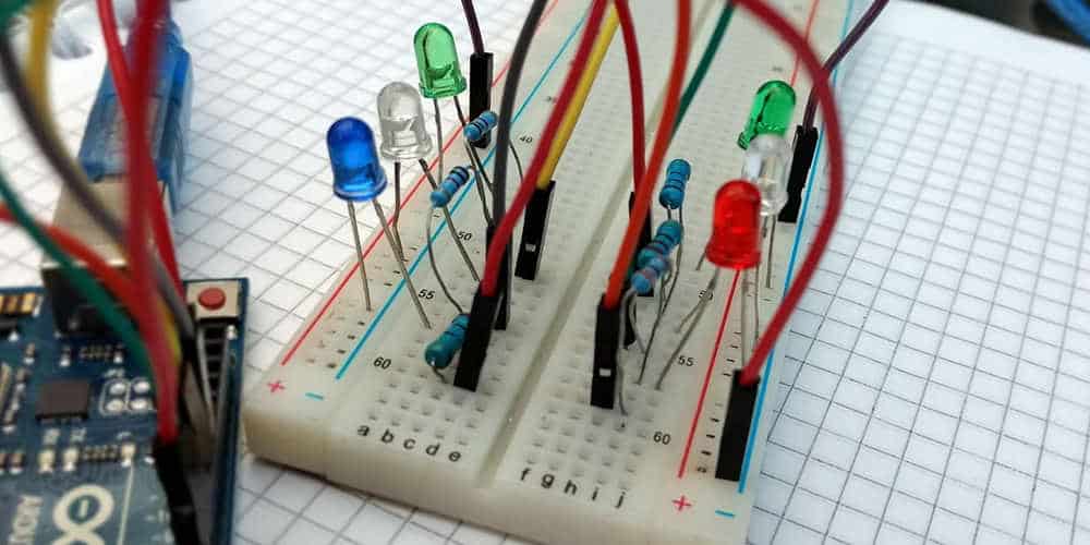
Rows and Columns
As you may have noticed, many breadboards have numbers and letters branded on different rows and columns. These serve no purpose other than to aid you in the construction of your circuit.
Circuits can quickly become complicated, and it only takes one erroneous leg of an electronic component to cause the entire circuit to fail. It’s much easier to plug a wire into the row number of the connection you’re trying to make if you know it rather than memorize it.
When using instruction booklets, these are also useful. It doesn’t matter if the circuits look the same or take up the same space on the breadboard when following instructions, as long as the connections are made.
Binding Posts
Some breadboards are manufactured and come prefixed on platforms that have things called binding posts. These binding posts allow you to make external connections with different kinds of power sources.
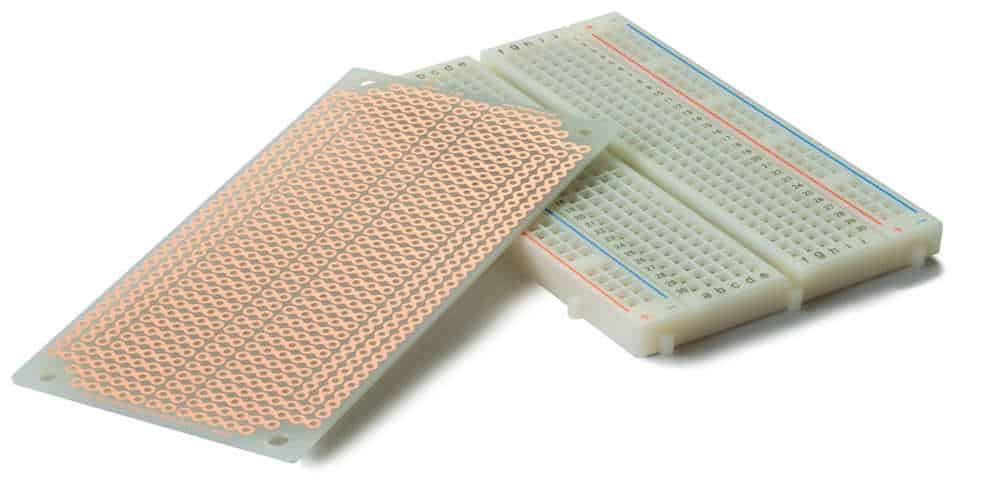
Although solderless breadboards are the more common type, there is yet another type of breadboard. These are solderable breadboards. These breadboards provide a permanent configuration for your electronic circuits.
They provide a more robust setup and include holes for electronic components such as copper tracing. These components can be soldered to the breadboard with a soldering iron to form an electrical connection via copper tracing.
Jumper wires must be soldered separately between these electrical components to create a lane through which current can flow. These breadboards come in a variety of sizes to suit your needs.
It is worth noting that a breadboard is not difficult to come by. A quick search on any online marketplace that sells electronics should yield a wide range of results to choose from. So, before you make a permanent investment in an electrical project using a permanent board, you should test your electronic circuits with suitable breadboards.
