Altium is a high-end PCB design software package that has gained popularity in the PCB industry. It is highly preferred among PCB manufacturers because of the design tools, features, and capabilities it offers. Some of its features are a PCB module, an auto-router, a differential pair routing, and a schematic.
Also, Altium is one of the most sophisticated PCB design software packages in the PCB electronics industry. This article serves as a guide on how to use Altium for your PCB design project. Also, you will get to learn the whole process of designing a printed circuit board.
What is Altium?
Altium designer is a PCB design software package that comprises a wide range of PCB design tools. This PCB designer is the most reliable design system due to its power and ease. Also, Altium designer is a cloud-based software integrated in 3D modeling, schematic capture, and assembly drawing.
Developed by Altium Limited, Altium Designer offers sophisticated design features. Also, you can use this software in design PCBs for several applications like medical devices and consumer electronics. It is ideal for professionals and hobbyists. Also, Altium is suitable for simple PCB projects and complex PCBs.
Altium designer connects PCB designers, manufacturers, and part suppliers to manufacture electronics products in a better and faster way. Also, engineers can have access to all the required design tools under one roof. Therefore, it makes the whole design process faster and as well offer high-quality design.
Altium keeps upgrading its features. Also, the latest version which is Altium Designer 20 is a product of several years of improvement and innovation dedicated to developing an integrated design tool. Therefore, it enables users to utilize advanced features for PCB design.
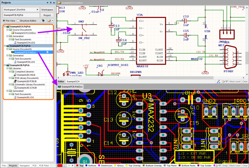
There are two different components in Altium Designer workspace. Also, these are the workspace panels and primary document editing environment. The workspace panels are on the left side of the tool while the document editing environment is on the right side of Altium Designer. You need a good PCB layout to achieve a successful PCB design. Also, Altium helps in creating a PCB layout and great project files.
Features of Altium Designer
Altium Designer offers a lot of features. Also, this is one of the reasons it is the most sought-after software.
Unified library management
The library in Altium comprises a collection of useful models and components. Also, this software package combines PCB footprints and schematic symbols, supply chain planning, and lifespan status in one location. Furthermore, users can have access to all collaboration tools for product development and project management.
Native 3D PCB design
The native 3D PCB design enables users to work around a three-dimensional PCB design. This new feature allows you to verify if your circuit board can fit well in the final product enclosure. Also, this feature helps to prevent any costly redesigns. Furthermore, 3D PCB views enable you to verify designs and as well make changes before sending the PCBs for manufacture.
PCB layout
The PCB layout features helps in creating an optimal layout. Also, this feature comprises sophisticated controls, native 3D support, and powerful stackup management. All of this gives you the control you need in your design environment.
Fabrication drawings
You can establish clear fabrication views of your PCB and components with Draftsman. All you need is to tap a few buttons, Viola!
ECAD/MCAD collaboration
Altium allows ECAD/MCAD collaboration. Therefore, syncing is possible with other CAD systems like Autodesk Inventor, SOLIDWORKS, and more.
Realistic rigid flex
The realistic rigid flex function offers case construction,3D components, and PCB clearances. All of these help you meet your mechanical needs in real-time.
Schematic capture
Altium features a wide range of design verification, wiring tools, and transparent netlist generation. These help you record your design.
Multi-board assembly
You need to know how different components of your product function in Native 3D. The multi-board assembly feature enables you to detect and repair board issues.
Benefits of Altium Designer
Altium PCB design software offers a lot of benefits which include:
Cloud-based platform
Altium is a cloud-based design tool that enables users to work remotely. This means that users can have access to this software from anywhere through the internet. Also, project team members cab edit and design their projects from anywhere.
Allows collaboration
Online collaboration can save time when there are design reviews. Also, having access to stakeholder’s feedback from any device helps a lot.
High density and high speed design
Engineers can easily develop high-speed electronics with the help of a strong tuning engine. Also, this software offers support to advanced pattern features. This includes impedance extraction and precise propagation delay.
User-friendly
Altium Designer is a user-friendly platform. Therefore, it is suitable for beginners and professionals. Also, this platform makes you have an enjoyable design experience.
Very versatile
This is one of the benefits users get to enjoy. Altium allows you to create various types of circuit boards. Giving attention to details, you can combine multiple projects. Also, this software can convert files from other platforms.
Error checking mechanisms
Altium doesn’t give any room for mistakes. It allows users to inspect errors and make corrections with the Native 3D visualization.
Advanced supply chain management
You can generate BOMs for your PCB project with this PCB design platform. Also, Altium gets rid of any confusion you might have with your manufacturer. Furthermore, Altium Designer centralizes all your manufacturing documents in one location. Therefore, it allows you easily access them. Also, this will help you to achieve a successful design. You will get to enjoy a stress-free tracking experience with the supply chain management.
Context-driven comments
Altium allows you to highlight problematic sections in the design and enables you tag individuals to address problems.
How to Download and Install Altium Designer
The first stage of integrating Altium in your PCB design is to download the software. Visit the Altium website and ensure you sign up for a free user account before you commence with the download process. Also, you will have to do this on the Altium website. After you have signed up, you can login to your account.
Verify the benefits and components of Altium Designer before you finally download. Click on the download page to download. Also, click on the Yes button to run the software on your computer. A page will pop up on your screen welcoming you to the installer. Then, click on the Next button to proceed. After this, go to the Design Functionality to select the preferred functionality and click on Next.
Now, select the computer folders to install your download and click on Next. After a while, you will see a Complete Installation panel. Now the download and installation have been successfully completed.
If you are running Altium Designer for the first time, you will see a License Management Panel. This implies that the license you are using is invalid. Also, to access valid permissions, you can sign in to the Altium account that was earlier created.
How to Set up Design Project
Create a new project
A PCB project is a design template that specifies and creates a PCB. To create a new project in Altium, you will need to use the File section, Click on File and choose New Project and select PCB Project tab.
Add schematic design to the Project
Here, you have to add a schematic to your project. You will have to create two different files. The first one will be for designing the PCB layout and the other for drawing the schematics.
Set the document options
You will need to set document options like Snap and sheet size before you start drawing your circuit board.
Component and libraries
You will need to add schematic symbols in the design capture. You can do this by making components and placing local libraries. Also, you can have access to components through the explorer window or the libraries window.
How to Place Components on the Schematic and Add PCB
Access the components and place them on any schematic file that is running. There are two ways to place components. When selecting a component, ensure the available footprint is ideal.
From the libraries window
With the Place tab, press to add the component on your cursor. After you have placed the components, leave the placement mode by right clicking. Also, you can place components on the Schematic directly from the Libraries panel by simply dragging the Schematic element. Ensure you hold your cursor and release it to place the component.
From the explorer window
You will need to click on the component and select Place. After then, place it well and press to insert. The explorer window will fade to help you view the schematic components.
Wire the schematics
You will need to wire your PCB when adding a board. Also, this will help create good connection between various parts. Click on the Enter bar to tie the wire.
Net and NetLabels
Net refers to every set of arts connected. For example, a net can comprise pin R1, base Q1, and C1. Also, Altium gives every net a label according to the component pin type. Also, you can introduce Net labels to simplify the basic nets. You can use NetLabels to connect components.
How to Transfer Schematic to PCB Editor
You can directly move the schematic from the schematic editor to the PCB editor. There is no need for another netlist document to enhance the transfer. Go to the Design section of the schematic editor and select Update PCB Document Multi-vibrator. PcbDoc. Also, another way to go about this is to move to the board editor and select Design and click on Import Changes Mult-vibrator. PrjPcb.
List each schematic component and its matching footprints. The software will try to identify each impression in the Content Vault if you integrate the ECOs. Also, Altium will generate schematic nets. This would be of help if you enabled the ECOs to relocate the nets to the PCB and introduce pins of every net. After this, you can move extra schematic data such as component classes.
How to Design the PCB
Add nets and components to the PCB file
To design your circuit board, you have to save the schematic file. While you are still in the schematics file, select Design and click on Update PCB Document. A window will pop up. Ensue you select all nets and schematic components. After this, click on validate changes. After this press execute changes.
Design the board shape
You will see a gray area and a black area. The black area is the circuit board. However, you can modify board shape. Click on drawing tool and choose Rectangle draw a small rectangle. When doing this, ensure all routes and components will fit the rectangle.
After this, choose the rectangle and click on Design board shape, and select Define Board Shape from already Selected Objects. Now that you have changed the board shape, place all components in the board and arrange as desired.
Mind the layers
You should know that circuit boards have a bottom side and a top side. While some circuit boards have some layers. During component placement, ensure you place the component in the right layer. As a beginner, you can place components on the top layer.
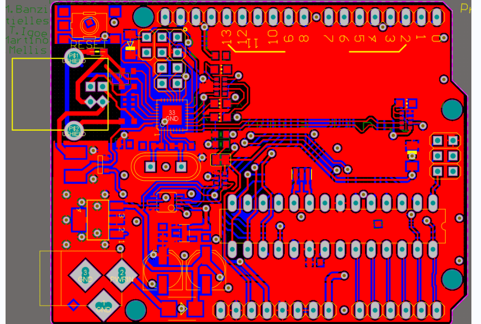
Route components in PCB
Now is time to route all components. Also, you must use the routing tool to achieve this. Click on the routing tool and select interactive routing.
Adjust PCB shape
Your PCB is almost ready at this stage. When you zoom and view the PCB, you will realize there is empty space. Therefore, you can edit the PCB shape. To do this, click on number Key 1 and input the board planning mode.
Add text
At this point, your circuit board is ready. Now, you can include images and text to your circuit board.
Conclusion
There are very few reliable PCB design software packages available. Altium Designer is one of such reliable packages. Also, this PCB design software comes with an intuitive user interface. In addition, Altium Designer was specially developed to make the entire PCB design process much easier and faster. With a wide array of design tools, you can have a great design experience.
