Multisim is a powerful software tool used for designing and simulating printed circuit boards (PCBs). It is widely used in the electronics industry for its ability to quickly and accurately model complex circuits, and to test and refine designs before they are built. With Multisim, designers can create and simulate circuits using a wide range of components, including resistors, capacitors, inductors, diodes, transistors, and integrated circuits.
Multisim’s intuitive interface and powerful simulation engine make it an ideal tool for both novice and experienced designers. Whether you are designing a simple circuit for a school project or a complex system for a commercial product, Multisim can help you quickly and easily test and refine your design. With its extensive library of components and its ability to simulate both analog and digital circuits, Multisim is a must-have tool for anyone involved in electronics design.
PCB Design Overview
What is PCB Design?
Printed Circuit Board (PCB) design is the process of creating a physical board that connects electronic components using conductive pathways. The design process involves placing components on the board and routing the connections between them. PCB design is essential for electronic devices to function correctly, and it plays a vital role in the development of modern technology.
Why is PCB Design Important?
PCB design is crucial because it ensures the proper functioning of electronic devices. Without proper PCB design, electronic devices would not be able to function correctly. PCB design also plays a significant role in the development of modern technology, as it allows for the creation of smaller, more efficient devices.
Multisim in PCB Design
Multisim is a software tool used in PCB design that allows for the simulation of electronic circuits. Multisim provides a user-friendly interface for designing, testing, and analyzing electronic circuits. The software allows for the creation of schematic diagrams, the simulation of circuits, and the layout of PCBs.
Multisim is an essential tool in PCB design because it allows for the simulation of circuits before they are physically built. This feature saves time and money by identifying potential issues before the circuit is built, reducing the need for costly redesigns. Additionally, Multisim allows for the optimization of circuit performance, ensuring that the circuit functions correctly and efficiently.
In summary, PCB design is a critical process in the development of electronic devices, and Multisim is a valuable tool that helps designers create efficient, functional circuits.
Multisim Basics
What is Multisim?
Multisim is a powerful circuit simulation software that allows you to design, test, and analyze electronic circuits. It is widely used in the industry and academia for both educational and professional purposes. Multisim is developed and marketed by National Instruments and provides a user-friendly interface that makes it easy for beginners to get started with circuit design.
How to use Multisim for PCB Design
Multisim provides a comprehensive set of tools for designing printed circuit boards (PCBs). Here are the basic steps for using Multisim for PCB design:
-
Create a schematic: Start by creating a schematic diagram of your circuit using Multisim’s schematic editor. This allows you to design the circuit and simulate its behavior before you start designing the PCB.
-
Generate a netlist: Once you have created the schematic, you can generate a netlist that describes the connections between the components in your circuit.
-
Create a PCB layout: Use Multisim’s PCB layout editor to create a layout of your circuit on a PCB. This involves placing the components and routing the traces that connect them.
-
Verify the design: Once you have created the PCB layout, you can use Multisim to verify the design and ensure that it meets your requirements.
-
Export the design: When you are satisfied with your design, you can export it to a format that can be used by a PCB manufacturer to fabricate the PCB.
Multisim also provides a range of advanced features for PCB design, such as autorouting, design rule checking, and 3D visualization. These features can help you to optimize your design and ensure that it meets your requirements.
In conclusion, Multisim is a powerful tool for PCB design that provides a user-friendly interface and a comprehensive set of features. By following the basic steps outlined above, you can use Multisim to design and simulate electronic circuits, and create high-quality PCB layouts.
PCB Design Process with Multisim

Schematic Capture
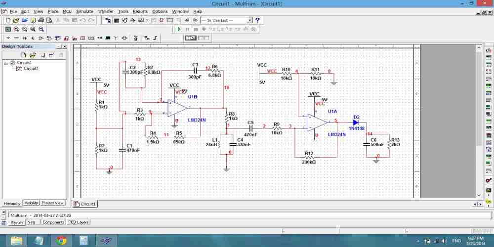
The first step in the PCB design process with Multisim is to create a schematic of the circuit. This can be done by dragging and dropping components from the Multisim library onto the schematic page. Once all the components are added, you can connect them using wires. Multisim offers a wide range of tools and features to help you create a clear and organized schematic.
Component Placement
After the schematic is complete, the next step is to place the components on the PCB layout. Multisim provides an auto-placement tool that can help you place the components quickly and efficiently. You can also manually place the components to achieve a more optimized layout. It’s important to consider factors such as signal integrity, power distribution, and thermal management when placing the components.
Routing
Once the components are placed, the next step is to route the connections between them. Multisim provides a powerful auto-router that can route the connections automatically. However, it’s recommended to manually route the critical connections to ensure better signal integrity. Multisim offers a wide range of routing tools and features to help you achieve a clean and optimized layout.
Gerber File Generation
The final step in the PCB design process with Multisim is to generate the Gerber files. These files contain the information needed to manufacture the PCB. Multisim provides a Gerber file generation tool that can export the necessary files in a variety of formats. It’s important to ensure that the generated files are error-free and ready for manufacturing.
In conclusion, Multisim provides a comprehensive set of tools and features to help you design a high-quality PCB. By following the above steps, you can create a well-organized and optimized layout that meets your design requirements.
Advanced Techniques in Multisim
Simulation and Analysis
Multisim offers a wide range of simulation and analysis features that can help designers validate their designs. One of the most powerful features of Multisim is its ability to perform Monte Carlo analysis, which allows designers to simulate the effects of component tolerances on their designs. This feature is particularly useful when designing high-precision circuits, where even small variations in component values can have a significant impact on circuit performance.
Another useful feature of Multisim is its ability to perform sensitivity analysis. This feature allows designers to identify the components in their designs that have the greatest impact on circuit performance. By identifying these components, designers can focus their efforts on optimizing these components to achieve the desired circuit performance.
Design Rule Checking
Multisim includes a powerful design rule checking (DRC) feature that can help designers ensure that their designs meet the requirements of their target manufacturing process. The DRC feature checks the design against a set of rules that define the minimum allowable spacing, trace widths, and other parameters. If the design violates any of these rules, Multisim will flag the violation and provide suggestions for how to correct it.
Design for Manufacturability
Design for manufacturability (DFM) is an important consideration in any PCB design. Multisim includes a number of features that can help designers optimize their designs for manufacturability. For example, the software includes a netlist export feature that allows designers to export their designs to popular PCB layout tools. Multisim also includes a 3D visualization feature that allows designers to visualize their designs in three dimensions, which can be helpful for identifying potential manufacturability issues.
In conclusion, Multisim is a powerful tool for PCB design that offers a wide range of advanced simulation, analysis, and design features. By leveraging these features, designers can optimize their designs for performance, manufacturability, and reliability.
