Water level indicators are a crucial component in various industrial and residential applications. A water level indicator PCB design is a printed circuit board that measures the water level in a tank or reservoir and sends information to a display unit. This technology is widely used in water treatment plants, irrigation systems, and home appliances such as washing machines and dishwashers.
The design of a water level indicator PCB involves several considerations, including the type of sensor used, the accuracy of the readings, and the power consumption of the circuit. The sensor can be based on different principles such as capacitive, ultrasonic, or optical. Each type of sensor has its advantages and disadvantages, and the choice depends on the specific application requirements. The accuracy of the readings is critical in applications where precise monitoring is necessary, such as in chemical processing plants or water treatment facilities. The power consumption of the circuit is also an essential factor, especially in battery-powered devices, where low power consumption is crucial to extend the battery life.
PCB Design
To design a water level indicator PCB, you need to follow a few basic steps. In this section, we will discuss the components required, schematic design, and PCB layout design.
Components Required
Before starting the PCB design, you need to gather all the required components. Here is a list of the components needed for a water level indicator PCB:
- Microcontroller (ATmega328P)
- Voltage regulator (LM7805)
- Resistors
- Capacitors
- LEDs
- Transistors
- Battery connector
- Water level sensor
Schematic Design
Once you have all the components, the next step is to design the schematic. The schematic design is a critical step in the PCB design process as it shows the connections between the components. Here are a few tips for designing the schematic:
- Use a software tool like Eagle or KiCad to design the schematic
- Place the components in a logical order
- Connect the components using wires or symbols
- Label the components and connections for easy identification
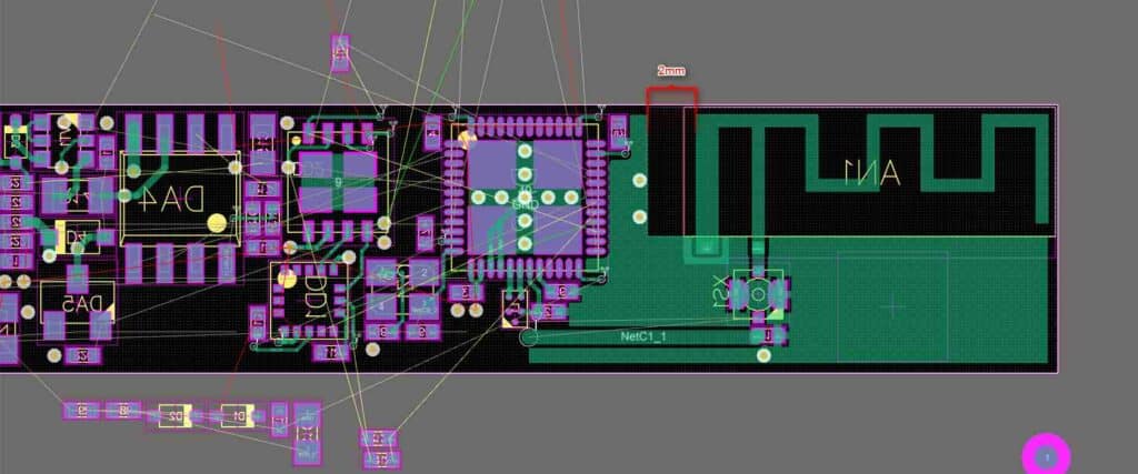
PCB Layout Design
After designing the schematic, the next step is to design the PCB layout. The PCB layout design is the actual physical representation of the circuit. Here are a few tips for designing the PCB layout:
- Use a software tool like Eagle or KiCad to design the PCB layout
- Place the components on the PCB in a logical order
- Route the connections between the components
- Follow the design rules to ensure proper spacing and trace width
- Add mounting holes and labels for easy identification
In conclusion, designing a water level indicator PCB requires careful planning and attention to detail. By following the steps outlined in this section, you can design a functional and efficient PCB.
Water Level Sensor

Types of Water Level Sensors
Water level sensors are available in different types based on the technology used. Some of the popular types of water level sensors are:
-
Float switches: These sensors use a float that moves up and down with the water level. When the float reaches a certain level, it triggers the switch to turn on or off.
-
Ultrasonic sensors: These sensors use sound waves to measure the distance between the sensor and the water surface. They are non-contact sensors and are suitable for tanks with corrosive or hazardous liquids.
-
Capacitive sensors: These sensors use the principle of capacitance to measure the water level. The sensor is placed at the top of the tank, and as the water level rises, the capacitance changes, which is detected by the sensor.
-
Pressure sensors: These sensors use the pressure of the water to measure the water level. They are suitable for tanks with high water pressure.
Selection of Water Level Sensor
The selection of the water level sensor depends on various factors like tank size, type of liquid, and the accuracy required. Here are some factors to consider while selecting a water level sensor:
-
Tank size: The size of the tank determines the type of sensor required. For small tanks, float switches are suitable, while for larger tanks, ultrasonic or capacitive sensors are preferred.
-
Type of liquid: The type of liquid in the tank affects the sensor’s material and construction. For corrosive or hazardous liquids, ultrasonic sensors are preferred, while for non-corrosive liquids, float switches or capacitive sensors can be used.
-
Accuracy required: The accuracy required depends on the application. For critical applications, high-precision sensors are preferred, while for general applications, standard sensors can be used.
In conclusion, selecting the right water level sensor is crucial for accurate measurement and control of water levels in tanks. The type of sensor selected should be based on the tank size, type of liquid, and the accuracy required.
Microcontroller
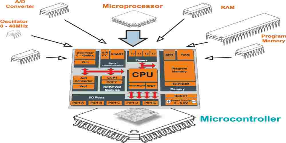
Selection of Microcontroller
The microcontroller is the brain of the water level indicator PCB design. It is responsible for controlling the sensors and displaying the water level. When selecting a microcontroller, it is important to consider factors such as the number of input/output pins, processing speed, and memory capacity.
One popular choice for water level indicator PCB designs is the Atmel AVR microcontroller. It has a wide range of input/output pins, high processing speed, and ample memory capacity. Other options include the PIC microcontroller and the ARM Cortex-M series microcontroller.
Programming the Microcontroller
After selecting the microcontroller, the next step is to program it. The programming language used will depend on the specific microcontroller chosen. Some popular programming languages for microcontrollers include C, C++, and Assembly.
The programming code for the microcontroller should include instructions for reading the sensor data and displaying the water level. It is important to ensure that the code is efficient and optimized for the specific microcontroller being used.
In addition to programming the microcontroller, it is also important to test and debug the code to ensure that it is functioning correctly. This can be done using a simulator or by connecting the microcontroller to the water level indicator PCB and testing it in a real-world environment.
Overall, selecting and programming the microcontroller is a crucial step in designing a water level indicator PCB. Careful consideration should be given to the specific requirements of the project to ensure that the chosen microcontroller is capable of meeting those requirements.
Power Supply
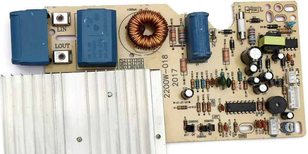
Selection of Power Supply Components
When designing a water level indicator PCB, selecting the right power supply components is crucial to ensure reliable performance. The power supply should be able to provide a stable voltage output with low noise and ripple.
The first step in selecting power supply components is to determine the required voltage and current output. This will depend on the specific components used in the circuit, as well as the desired functionality of the water level indicator.
Once the required voltage and current output have been determined, the next step is to select the appropriate voltage regulator. A linear voltage regulator is a common choice for water level indicator PCBs, as it provides a stable output voltage with low noise and ripple. However, a switching voltage regulator may be a better choice if space and efficiency are a concern.
Other important power supply components to consider include capacitors, inductors, and diodes. Capacitors can help filter out noise and ripple in the power supply, while inductors can help reduce electromagnetic interference. Diodes are used to protect the circuit from reverse voltage and voltage spikes.
Power Supply Design
After selecting the appropriate power supply components, the next step is to design the power supply circuit. The circuit should be designed to provide a stable voltage output with low noise and ripple.
One common way to achieve this is to use a voltage regulator circuit with filtering capacitors. The voltage regulator will provide a stable output voltage, while the capacitors will help filter out noise and ripple.
It is also important to consider the physical layout of the power supply circuit. The power supply components should be placed as close as possible to the voltage regulator to minimize noise and interference. Ground planes should also be used to provide a solid ground connection.
In summary, selecting the right power supply components and designing a stable power supply circuit is crucial for reliable performance of a water level indicator PCB.
