Analog and digital circuit design are two fundamental approaches to designing electronic circuits. Analog circuits work with continuous signals, while digital circuits work with discrete signals. Each approach has its advantages and disadvantages, and choosing the right one depends on the specific application.
Analog circuits are used in applications where accuracy and precision are important, such as in audio and video systems, power supplies, and sensors. These circuits work with signals that vary continuously over time, and they use components such as resistors, capacitors, and inductors to manipulate these signals. Analog circuits are often more complex than digital circuits, but they can provide higher levels of accuracy and precision.
Digital circuits, on the other hand, are used in applications where speed and efficiency are important, such as in computers, communication systems, and control systems. These circuits work with signals that have only two states, typically represented by the binary digits 0 and 1. Digital circuits use components such as logic gates, flip-flops, and registers to manipulate these signals. Digital circuits are often simpler than analog circuits, but they can provide faster and more efficient processing.
Analog Circuit Design
Analog circuit design is the process of designing circuits that operate on continuous signals. These signals can be voltage, current, or any other physical quantity that varies continuously over time. Analog circuits are used in a wide range of applications, including audio and video equipment, power supplies, and control systems.
Op-Amp Circuit Design
Op-amps are widely used in analog circuit design due to their versatility and ease of use. An op-amp is a high-gain amplifier that can be configured to perform a wide range of functions, including amplification, filtering, and signal conditioning.
When designing op-amp circuits, it is important to consider the following factors:
- Gain: The gain of an op-amp circuit determines the amount of amplification that is applied to the input signal.
- Bandwidth: The bandwidth of an op-amp circuit determines the range of frequencies that can be amplified.
- Noise: Op-amps are sensitive to noise, so it is important to minimize noise sources in the circuit design.
- Stability: Op-amp circuits can become unstable if the gain is too high or if the feedback loop is not properly designed.
Filter Circuit Design
Filter circuits are used to remove unwanted frequencies from a signal. There are two main types of filter circuits: passive filters and active filters.
Passive filters use only passive components, such as resistors, capacitors, and inductors, to filter the signal. Passive filters are simple and inexpensive, but they have limited performance.
Active filters use op-amps and other active components to filter the signal. Active filters can achieve higher performance than passive filters, but they are more complex and expensive.
When designing filter circuits, it is important to consider the following factors:
- Filter type: There are many types of filters, including low-pass filters, high-pass filters, band-pass filters, and notch filters. The choice of filter type depends on the specific application.
- Filter order: The order of a filter determines the steepness of the filter’s roll-off. Higher-order filters have steeper roll-offs and better performance, but they are more complex.
- Cutoff frequency: The cutoff frequency is the frequency at which the filter begins to attenuate the signal. The cutoff frequency is determined by the filter type and order, as well as the specific application requirements.
Digital Circuit Design
Digital circuits are electronic circuits that operate on digital signals. Digital circuits are used in a wide range of applications, from simple logic gates to complex microprocessors. In this section, we will discuss the design of digital circuits, including logic gate circuit design, flip-flop circuit design, and counter circuit design.
Logic Gate Circuit Design
Logic gates are the basic building blocks of digital circuits. They perform logical operations on one or more binary inputs to produce a single binary output. There are several types of logic gates, including AND, OR, NOT, NAND, and NOR gates.
To design a logic gate circuit, you need to first determine the logic function that you want the circuit to perform. You can then use a truth table to determine the input-output relationship for the logic function. Once you have the truth table, you can use Boolean algebra to derive the logic gate circuit.
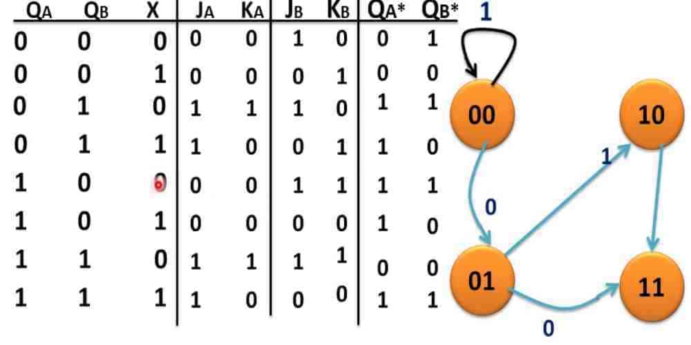
Flip-Flop Circuit Design
Flip-flops are digital circuits that can store a single bit of information. They are used in sequential logic circuits to store data and control the flow of data between different parts of the circuit. There are several types of flip-flops, including D flip-flops, JK flip-flops, and T flip-flops.
To design a flip-flop circuit, you need to first determine the type of flip-flop that you want to use. You can then use a truth table to determine the input-output relationship for the flip-flop. Once you have the truth table, you can use logic gates to implement the flip-flop circuit.
Counter Circuit Design
Counter circuits are digital circuits that count the number of clock pulses that they receive. They are used in a wide range of applications, including frequency dividers, timers, and digital clocks. There are several types of counter circuits, including binary counters, decade counters, and ring counters.
To design a counter circuit, you need to first determine the type of counter that you want to use. You can then use a truth table to determine the input-output relationship for the counter. Once you have the truth table, you can use flip-flops and logic gates to implement the counter circuit.
Mixed Signal Circuit Design

Mixed signal circuit design involves the integration of both analog and digital circuits on the same chip. This combination of circuits allows for the processing of both analog and digital signals, making it an essential part of modern electronic devices.
Analog-to-Digital Conversion
Analog-to-Digital Conversion (ADC) is the process of converting an analog signal into a digital signal. This process is used in many applications, including audio and video recording, medical equipment, and industrial control systems. ADCs are designed to accurately capture the analog signal and convert it into a digital signal that can be processed by a digital circuit.
One common type of ADC is the Successive Approximation ADC. This type of ADC uses a binary search algorithm to determine the digital value of the analog signal. The analog signal is compared to a reference voltage, and the result is used to determine the next bit of the digital signal. This process is repeated until the entire analog signal has been converted to a digital signal.
Digital-to-Analog Conversion
Digital-to-Analog Conversion (DAC) is the process of converting a digital signal into an analog signal. This process is used in many applications, including audio and video playback, motor control, and communication systems. DACs are designed to accurately reproduce the digital signal as an analog signal that can be output to a speaker or motor.
One common type of DAC is the R-2R ladder DAC. This type of DAC uses a network of resistors to convert the digital signal into an analog voltage. The digital signal is applied to the input of the DAC, and the output voltage is determined by the ratio of the resistors in the ladder network.
Overall, mixed signal circuit design is a critical part of modern electronics. The combination of analog and digital circuits allows for the processing of both analog and digital signals, making it possible to create complex electronic systems.
Circuit Simulation and Analysis
SPICE Simulation
One of the most important tools for circuit design and analysis is SPICE (Simulation Program with Integrated Circuit Emphasis). SPICE is a software tool that is used to simulate and analyze analog and digital circuits. It is used to predict the behavior of circuits before they are built, which helps to reduce design time and costs.
SPICE simulations are based on mathematical models that describe the behavior of electronic components such as resistors, capacitors, and transistors. These models are used to simulate the behavior of circuits under different conditions, such as varying voltage and frequency.
SPICE simulations can be used to evaluate circuit performance, identify potential problems, and optimize circuit design. They can also be used to test different circuit configurations and compare their performance.
Frequency Response Analysis
Frequency response analysis is a technique used to analyze the behavior of a circuit over a range of frequencies. This technique is used to determine the frequency response of a circuit, which is the relationship between the input and output signals of the circuit as a function of frequency.
Frequency response analysis is used to evaluate the performance of a circuit in different frequency ranges. It is used to determine the bandwidth of a circuit, which is the range of frequencies over which the circuit can operate effectively.
Frequency response analysis can also be used to identify potential problems in a circuit. For example, it can be used to identify resonant frequencies that can cause unwanted oscillations in the circuit.
In conclusion, circuit simulation and analysis is an essential part of circuit design. SPICE simulation and frequency response analysis are two important techniques used to evaluate the performance of analog and digital circuits. These techniques help to reduce design time and costs, and improve circuit performance and reliability.
PCB Design
When designing a printed circuit board (PCB), there are two main stages: schematic capture and layout design.
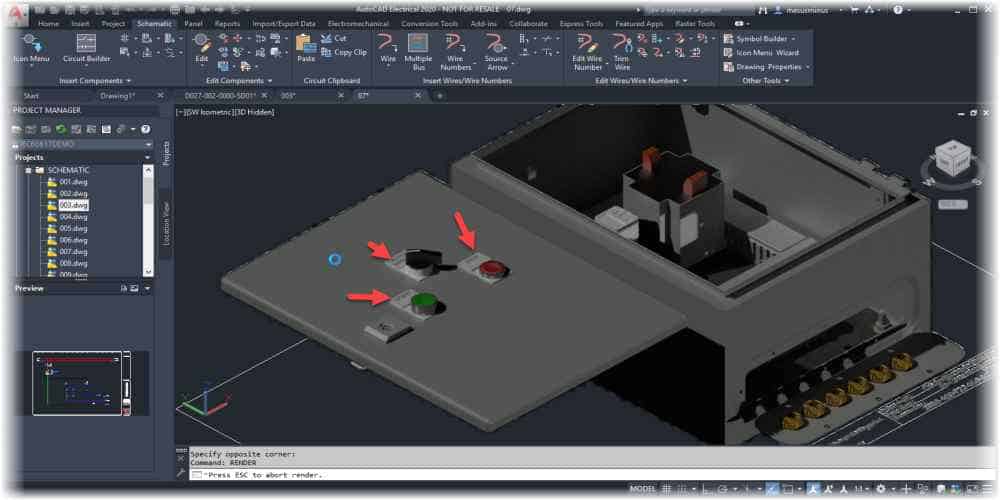
Schematic Capture
In schematic capture, the circuit is drawn using a software tool. This is where the components are placed and connected together. The schematic is used as a reference for the layout design stage.
It is important to ensure that the schematic is accurate and complete. This will help to avoid errors in the final design. It is also important to follow best practices for schematic design, such as using consistent component symbols and labeling.
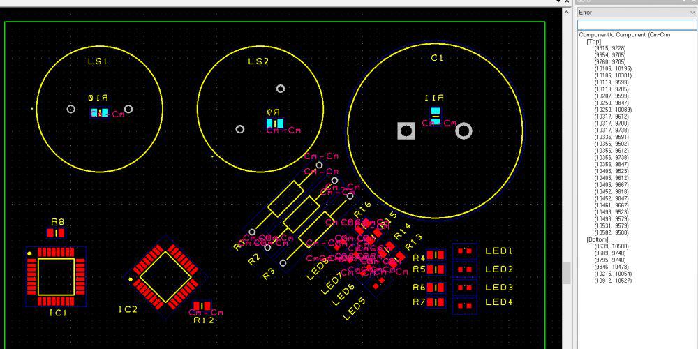
Layout Design
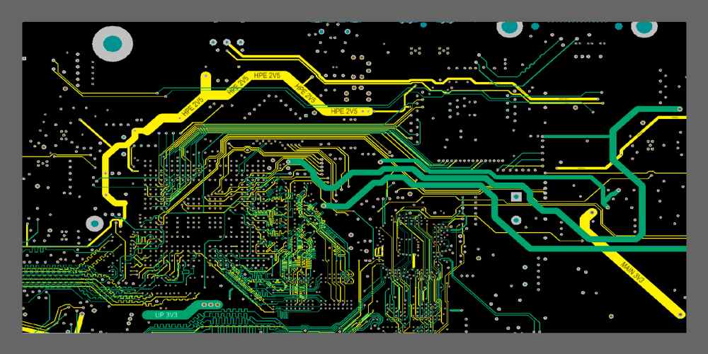
In layout design, the physical layout of the circuit is created. This involves placing the components on the PCB and routing the connections between them.
When designing the layout, it is important to consider factors such as signal integrity, power distribution, and thermal management. The layout should also be optimized for manufacturability.
There are various tools available for PCB layout design, such as Altium, Eagle, and KiCAD. These tools provide features such as design rule checking, auto-routing, and 3D visualization.
Overall, PCB design is a critical stage in electronic product development. Proper design can lead to improved performance, reliability, and manufacturability.
