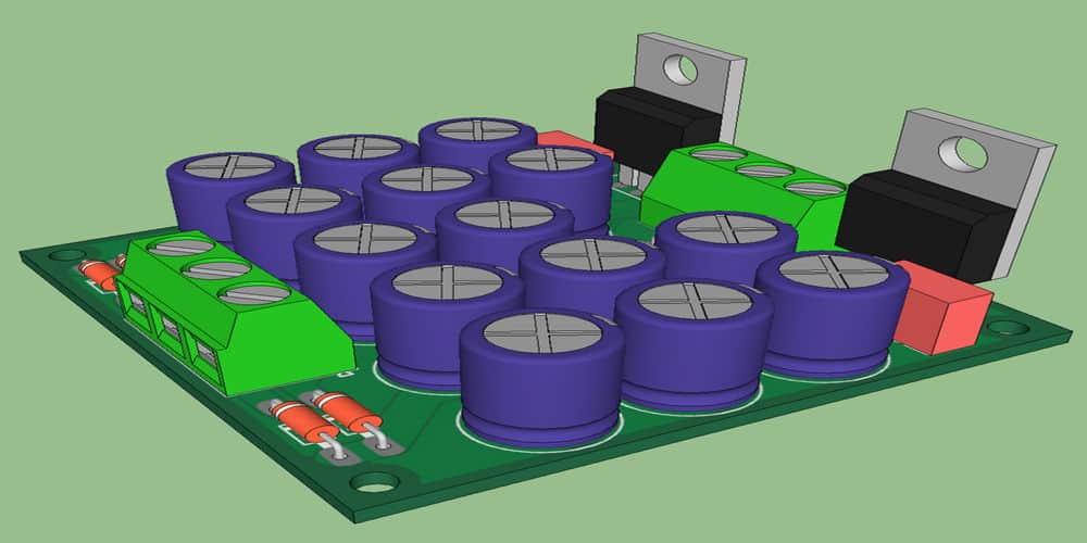
The printed circuit board is the heart of any electronic machine. Today you can’t imagine any device without a PCB design. When there were no printed circuit boards, engineers or designers connected all components on a circuit board using external wires. That’s why these circuits were complex and the boards were too large. It was also hard to build reliable connections on the control panel. It was hard to make complex machines and devices. With the invention of printed circuit boards, things became easy and hassle-free.
Nowadays, several designing tools and software help with PCB design. This software is available both offline and online. Every software comes with different features and usabilities. So it’s hard to decide which is best of all. As a result, many beginners and new designers may get confused. This article will help you to know about reliable PCB design software.
EAGLE is quite famous nowadays. This software is widely used for PCB designing and is compatible with every operating system. Most of the software is only compatible with some of the systems. That’s why many designers are reluctant to use them.
What is EAGLE?
Easily Applicable Graphical Layout Editor, aka EAGLE, is a very famous software. It is standard CAD software for PCB designing. Nowadays, it’s popular among engineers and PCB designers.
That’s why nowadays its popularity is increasing. It is simple and easy to use. Its interface is user-friendly. Furthermore, it contains a large number of electrical and electronic components. That’s why EAGLE is the first choice of all engineers and professionals for printed circuit board design. It is compatible with all windows so that you can run it on any operating system. For example, Linux and MAC system. If you are a beginner, you can also use its free version. So the EAGLE project is easy to handle.
It has two editors. One is a Schematic layout editor. It helps in designing the schematic layout. The other one is a PCB layout editor. The schematic layout editor does several functions and many unique features. It adds and connects all components according to the requirements. It also has many other features like modular design and multilayer schematic. In the paid version, you can use many advanced features to design a multilayer PCB.
After that, it converts into a PCB layout editor. It helps in setting components according to the rule check. It has alignment tools. That’s why it is easy to set the components appropriately. According to electric rules, some components don’t go well with some other electronic components. As a result, you have to compromise on the board’s efficiency. PCB layout editor helps you to design the best board layout.
How Does EAGLE Work for PCB Creation?
PCB designing and creation need a lot of attention and hard work. The final product depends upon the initial design. If your PCB design has faults, then you have to compromise on the quality of the final product. A low-quality PCB board affects the machine’s efficiency. To design the best quality board layout, you must have the best design software. EAGLE is one of the best designing software. Its UI is friendly and easy to navigate.
First of all, install Autodesk EAGLE in your system; it is available both in paid and freeware versions. The paid version is available for thousands of dollars per year. The paid version has many advanced features and access to the latest updates. That’s why professionals and experts like to use the professional version. It also provides technical support that includes call, mail, and online chat support. Community support is the icing on the cake. You can download the freeware version from Autodesk EAGLE’s official website. After downloading, you just have to run the package and complete the installation. Free versions are the best practice at the beginner level. That’s why many new learners go for the free version.
What Is a Control Panel

After installation now, you are ready to work with EAGLE. Click on the software icon, and it will open. Control Panel is the main Window. It is responsible for the proper functioning of the software. If you close the control panel, then every other Window related to the software will also close. That’s why it is necessary to focus on it as a beginner. You can spend some time on the control panel to get familiar. This software can help you to make Gerber files for PCB. Some people call this Gerber file a blueprint of PCB.
How Does It Work?
EAGLE’s UI is easy to use. As a result, the first page you see is a control panel. It contains different folders, name documents, libraries, and a design rule. Libraries contain a large list of different electrical components like resistors, capacitors, nets, etc. It can download new components if you need them. If you are working on an innovative circuit and the library doesn’t have a specific part. There is no need to worry. In paid versions, the library can download new components instantly. The free version has a limited option. You may not avail of this facility.
The next folder is the design block. This block has designed templates. Beginners can use this design template easily to design their printed circuit board. You can add these designs directly to your EAGLE project. Design rules help to follow all the basic rules. Design templates make things easy for beginners. You don’t have to work from scratch.
User Language Programs are another important feature. It helps to access data structure. Scripts have text files with EAGLE commands. It helps to automate many tasks. Projects contain EAGLE project details made by the user. You can customize your project details easily. You can save your projects for later use.
If you are a beginner, then you must spend some time on the control panel. In this way, you can learn about its important functions. It is necessary to understand that.
Schematic Window and how does it work
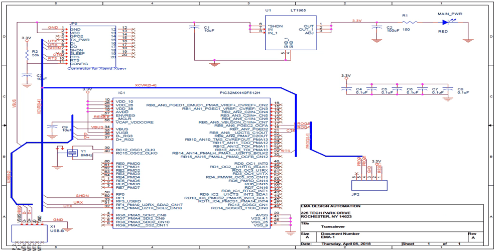
In The schematic Window, you can create and edit. It is the window where you create and edit schematic diagrams. That’s why it is necessary to have a good understanding of all the parts that you have to put on your circuit.
From the control panel, select the file and save it as a new project folder. Right-click on your project folder and select the new schematic sheet for your project. Before proceeding further, you can save this file and give it a name. You can name files according to PCB design.
If you are using the paid version, then you can see the area of a sheet with complex schematics. You can create complex designs there. If you are using freeware, ignore it.
In freeware, you have some limited options for designs. Once you have made your Schematic ready then may realize that you have to make some changes. Then you can make changes. You can take a design from the library for better. Once you are ok with your Schematic, and then closely look at it to find the flaws. In this way, you can make a better design.
It’s Time For The Electrical Rules Check.
There is always a chance for improvement, and you can neglect some flaws too. As a result, you may end up with the wrong Schematic. If you PCB based on the wrong Schematic, then you have to bear consequences later.
The rule of thumb to find the flaws and mistakes is to use Electrical Rules Check (ERC). It means that EAGLE has good knowledge of various parts. If there are errors, you may have a warning or error identification box. It helps you to check if anything unusual is going on. It helps you to know if there is any unconnected input pin. According to electrical rules, you can’t connect certain electronic components together. That’s why an electrical rule check is crucial.
Board View Window And How Does It Work?
Its appearance is the same as the schematic Window. You move around in the board window just like in the schematic Window. It will help you to check layers both ways. It is easy to check the top and bottom layers separately or simultaneously. If you want to isolate the top layer, click the layer button and click the none. Then select layers one by one, such as top layers, pads, unrouted holes, etc., the same procedure you can repeat for the bottom layers.
Adding And Connecting Parts In The Schematic
Click on the Add button to add parts to the Schematic. You can take help from the library. For example, you can add a resistor from the resistor library. Similarly, you can add LEDs from the resistor library. The library can help you a lot, that’s why it is necessary to have complete know-how of the software. If you are using it for the first time, you must spend time on the free version. Similarly, you can take help from the community.
Now it’s time to connect the parts on the layout. Use the NET command to connect all the parts. Don’t use the wire command. The net will continue being drawn with a single click on the net command. You can change the way the net is by right-clicking. Don’t double-click while going for the NET command. It can start from anywhere. That’s why it is necessary to pay attention during this task.
Labeling And Assigning Some Values To Parts
Labeling the parts and nets make things easy and straightforward. As a result, anyone can know about the parts and connections quickly. You can mark them with meaningful names. It makes routing the board easy. Label all of the resistors and the capacitor with the appropriate value.
Create A Board Layout
It is not tough to create the board layout. Go to the files and switch them to the boards. As a result, a dialogue box will appear with a statement that the board doesn’t exist. Click yes to create the board. With the board file, a box will come with all the parts. You need to group up all the parts logically. As a result; you create a perfect board.
Ground Plane And Route The Parts
It is a crucial step. Run the Polygon command to make the ground plane. The ground plane is very useful. It uses all unused space on a board and connects it to the ground net. You can use the route command for routing purposes. Working with the EAGLE is easy and time-saving. You can do plane modifications also.
Design Rule Check
The Design Rule Check (DRC) checks the board you designed against a set of rules to determine if you made any errors. It will catch many common mistakes in electrical connections. As a result, you find a chance for improvement.
When the Design Rules Check, the result comes, you can make the necessary changes in surface mount parts. If there is a problem with the width, then you can adjust the width. You can change the problematic connection in your design. Furthermore, it can also detect the unrouted traces crossing. In this way, you can get the perfect design.
Finally, You Have Done It.
Your routing has been completed. You have done the design rule check. Now you’re on track. You can create a zip file for your Gerber files. As a result, the software automatically creates the Gerber files. You must need these Gerber files for the manufacturing of your board.
Things To Keep In Mind
The following tips will help you to design a better board layout for PCB.
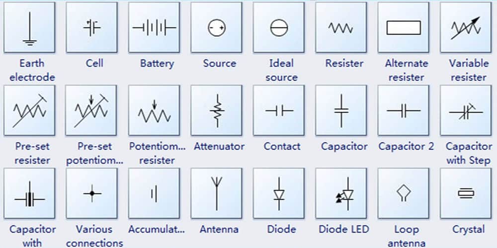
Know Your Symbols Clearly.
Symbols play an important role when using any PCB designing software. Whether you are using freeware or paid full versions, you must know about the related symbols. In this way, you can work easily on EAGLE. There are plenty of symbols, so it’s hard to keep all of them in mind. If you are working on international Schematic, then it is tough to remember all symbols. That’s why it is a good idea to learn these relevant symbols. Initially, you may have some problems, but later it will save you time.
Activating Your Libraries
Libraries are a big support for PCB designers. These allow you to not start from scratch. If you are using EAGLE for the first time, then you have to activate all the libraries. These libraries are not activated by default. To activate these libraries, go to the control panel. As most of the parts you need for your design have already been created by someone else, you don’t have to spend time making them yourself. As a result, you can save a lot of time with the help of these libraries. Similarly, your work can help other users.
You Can Add, Delete And Relocate The Parts.
Once you have done with your Schematic, you want to delete some unnecessary parts. There is a delete icon on the left- side of the EAGLE UI. You can delete duplicate or unnecessary parts. Similarly, you can relocate the parts to make the Schematic more ideal. There is a rotate button on the left side. Use this button to rotate, relocate and edit parts to improve connectivity.
Pay Attention to The EAGLE Warning During The Electrical Rule Check.
If you connect the wrong parts with each other then problem arise. As a result, EAGLE gives you a warning. If you connect parts having voltage differences, then once again, EAGLE gives you a warning. These warnings help you to re-check your lost electrical connection. As a result, you get a better design.
Pay Attention to The Reference Voltage And DRC Errors.
If parts are not connected according to the reference voltage, you may face problems. Similarly, eliminating DRC errors helps you to design a better board layout. As a result, you make the perfect layout or PCB design. Above all, you should focus on component arrangements according to voltage.
Why Is Autodesk EAGLE So Famous For Designing PCB?
You can run EAGLE on any platform, any window, and MAC. Although there are many software’s, sometimes their compatibility becomes an issue for the users.
Autodesk EAGLE software is lightweight with so many advanced tools. Many other PCB design tools or software are too heavy and slow down the system. The installer is about twenty-five MB. As a result; you have a smooth experience.
Autodesk EAGLE’s freeware version also offers you maximum utility. Its paid version comes with many tools and other advanced features. You can design a PCB Even from its free version. That’s why people like to use EAGLE.
It offers community support. The Autodesk EAGLE community is always ready to support new users. If you have a design problem or need technical support, the Autodesk EAGLE community is here to help you. In addition, you can connect with them by chat and email. Above all, EAGLE is the first choice of many professionals.
Wrapping Up the Things
The printed circuit board is a necessity of all modern machines and devices. That’s why it is necessary to pay attention to their designs. There is new software and tools for printed circuit board design every day. Undoubtedly EAGLE is one of the best PCB design software. You can use its free version if you are in the learning phase. If you are a professional designer, then you may need its paid version. The professional version has many advanced tools, features, and, furthermore, community support. Community helps you to sort out many things related to PCB and software. In conclusion, we can say that EAGLE has the edge over many other tools
