Inkscape is a popular open-source vector graphics editor that is widely used for creating illustrations, logos, icons, and other graphical elements. However, many people are not aware that Inkscape can also be used for designing printed circuit boards (PCBs). In fact, Inkscape has a number of features that make it an excellent tool for creating PCB designs.
One of the main advantages of using Inkscape for PCB design is its ability to handle vector graphics. This means that you can easily create complex shapes and designs that are precise and scalable. In addition, Inkscape has a number of tools that can help you create and manipulate paths, nodes, and other elements that are essential for designing PCBs. With these tools, you can create custom shapes and layouts that are tailored to your specific needs.
Another advantage of using Inkscape for PCB design is its flexibility. Inkscape is a cross-platform application that runs on Windows, Mac OS X, and Linux, which means that you can use it on almost any computer. In addition, Inkscape is open-source software, which means that it is free to use and distribute. This makes it an excellent choice for hobbyists, students, and anyone else who is looking for an affordable and powerful PCB design tool.

Inkscape PCB Design Basics
What is Inkscape?
Inkscape is a free and open-source vector graphics editor that can be used for a variety of design tasks. It is a powerful tool that allows you to create and edit vector graphics, including those used in PCB design. Inkscape has a user-friendly interface that makes it easy to use and learn, and it is compatible with a wide range of operating systems.
What is PCB Design?
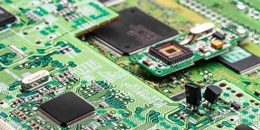
PCB design is the process of creating a printed circuit board (PCB) that connects electronic components together. PCBs are used in a wide range of electronic devices, from smartphones to computers to medical equipment. PCB design involves creating a schematic diagram of the circuit, laying out the board, and then designing the traces that connect the components together.
How to Use Inkscape for PCB Design
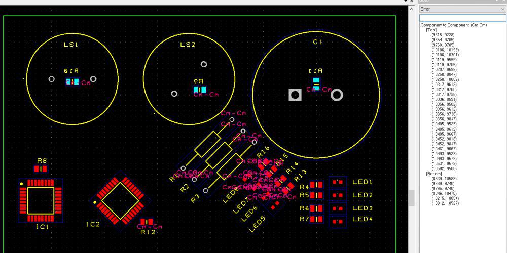
Inkscape can be used for PCB design by creating vector graphics of the PCB layout. This can be done by importing a schematic diagram into Inkscape and then laying out the board using the tools and features available in Inkscape. Some of the features that make Inkscape ideal for PCB design include:
- Layers: Inkscape allows you to create multiple layers within a single document, which is useful for separating different aspects of your design.
- Snap to Grid: Inkscape has a snap-to-grid feature that makes it easy to align components and traces.
- Path Editing: Inkscape allows you to edit paths and shapes with precision, which is useful for creating complex designs.
- Export Options: Inkscape allows you to export your design in a variety of formats, including SVG, PDF, and PNG.
Overall, Inkscape is a powerful tool that can be used for PCB design. With its user-friendly interface and powerful features, it is an excellent choice for anyone looking to create high-quality PCB designs.
Creating a PCB Layout in Inkscape

Setting Up the PCB Layout
Before starting the PCB layout, it is essential to set up the correct document properties in Inkscape. Go to File > Document Properties and set the document size to the required dimensions of your PCB. It is also important to set the units to millimeters and the grid size to match the pitch of the components.
Adding Components to the PCB Layout
To add components to the PCB layout, it is recommended to use the Inkscape extension called PCBmodE. This extension allows you to add components from its library directly to the PCB layout and also provides the necessary footprints for each component.
Designing the Traces
To design the traces, use the Bezier curve tool to draw the traces between the components. It is important to keep the traces as short as possible to reduce signal degradation and interference. Use the grid to ensure that the traces are aligned correctly and have the correct spacing.
Creating the Copper Pour
To create the copper pour, draw a rectangle around the PCB layout and fill it with the copper color. Then, use the Path > Object to Path command to convert the rectangle into a path. Next, select the path and go to Path > Union to merge it with the PCB layout. Finally, use the Path > Division command to cut out the copper pour where the traces are located.
In conclusion, Inkscape is a powerful tool for designing PCB layouts. By following the steps outlined above, you can create a professional-looking PCB layout that is ready for fabrication.
Exporting the PCB Design
Exporting Gerber Files
To export Gerber files from Inkscape PCB, you need to open the PCB design file and click on “File” in the top left corner. Then, select “Export” and choose “Gerber” as the file type. In the Gerber export settings, you can choose the layers you want to export, the units of measurement, and the precision.
It is important to note that different PCB manufacturers may have different requirements for Gerber files, so make sure to check with your manufacturer before exporting.
Exporting Drill Files
To export drill files from Inkscape PCB, you need to open the PCB design file and click on “File” in the top left corner. Then, select “Export” and choose “Drill” as the file type. In the drill export settings, you can choose the units of measurement and the precision.
Like with Gerber files, it is important to check with your manufacturer for any specific requirements for drill files.
Exporting the Bill of Materials
To export the Bill of Materials (BOM) from Inkscape PCB, you need to open the PCB design file and click on “File” in the top left corner. Then, select “Export” and choose “BOM” as the file type. In the BOM export settings, you can choose which components to include and the format of the BOM file.
Exporting the BOM can be useful for keeping track of the components needed for your PCB design and for ordering parts from suppliers.
Overall, Inkscape PCB makes it easy to export the necessary files for manufacturing your PCB design. Just make sure to check with your manufacturer for any specific requirements.
Advanced Techniques in Inkscape PCB Design

Using Inkscape Plugins
Inkscape is a powerful tool for designing PCBs, but it can be made even more powerful with the use of plugins. Plugins can help automate repetitive tasks, add new features, and improve overall workflow. Some popular plugins for Inkscape PCB design include PCB-Rnd, PCB Layout, and SVG2Shenzhen.
PCB-Rnd is a plugin that allows for the creation of custom footprints and symbols, as well as the import and export of Gerber files. PCB Layout is a plugin that provides a more traditional PCB design interface, complete with layers, grids, and snap-to functionality. SVG2Shenzhen is a plugin that can convert Inkscape designs into files compatible with popular PCB manufacturers like Seeed Studio and JLCPCB.
Creating Custom Components
Inkscape allows for the creation of custom components, which can be useful for designing unique PCBs. Custom components can be created using the Path tools, as well as by importing SVG files. It’s important to ensure that custom components are properly sized and aligned, and that they have the correct pinout and footprint.
Designing Multi-Layer PCBs
Inkscape can be used to design multi-layer PCBs, which can be useful for more complex designs. Multi-layer PCBs can be created by stacking multiple PCB designs on top of each other, with each layer representing a different circuit. It’s important to ensure that the layers are properly aligned and that the correct trace widths and clearances are used.
In conclusion, Inkscape is a versatile tool for PCB design, and with the use of plugins, custom components, and multi-layer design techniques, it can be made even more powerful. By taking advantage of these advanced techniques, designers can create unique and complex PCBs with ease.

