The Oppo A3s is a popular smartphone that has gained a reputation for its sleek design and impressive features. However, what many people do not know is that the phone’s Printed Circuit Board (PCB) layout plays a crucial role in its performance. The PCB layout determines how the phone’s components are connected and how they communicate with each other.
The Oppo A3s PCB layout is designed to optimize the phone’s performance and ensure that it runs smoothly. The layout is carefully crafted to ensure that the phone’s components are arranged in the most efficient way possible, minimizing the risk of interference and maximizing the phone’s processing power. This attention to detail results in a phone that is not only powerful but also reliable.
In this article, we will take a closer look at the Oppo A3s PCB layout and explore how it contributes to the phone’s performance. We will examine the various components of the PCB and how they are arranged, as well as the benefits of this layout for the phone’s overall functionality. By the end of this article, you will have a better understanding of how the Oppo A3s PCB layout works and why it is an important factor to consider when choosing a smartphone.
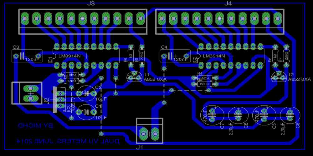
Oppo A3s PCB Layout Overview
The Oppo A3s is a budget smartphone that features a PCB layout that is well-designed and optimized for performance. The PCB layout is the foundation of the phone’s hardware and is responsible for the proper functioning of all its components.
The Oppo A3s PCB layout is designed to maximize the use of space on the board while ensuring that all components are optimally placed for efficient performance. The PCB is divided into different sections, each dedicated to a specific component or group of components.
The main components of the Oppo A3s PCB layout include the processor, RAM, storage, battery, display, camera, and audio components. These components are strategically placed on the board for optimal performance and efficient use of space.
The PCB layout also features a number of connectors and ports, including the charging port, headphone jack, and SIM card slot. These connectors are placed in convenient locations for easy access and use.
Overall, the Oppo A3s PCB layout is well-designed and optimized for performance. It ensures that all components work together seamlessly to provide a smooth and efficient user experience.
PCB Components
The Oppo A3s PCB layout consists of several components that are responsible for the proper functioning of the device. Here are some of the main components that you may find on the PCB:
- Processor: The Oppo A3s is powered by a Qualcomm Snapdragon 450 processor, which is responsible for executing all the instructions and commands given by the user.
- Memory: The device comes with 2GB of RAM and 16GB of internal storage, which can be expanded up to 256GB using a microSD card.
- Power Management Unit (PMU): The PMU is responsible for managing the power supply to all the components on the PCB. It ensures that each component receives the right amount of power, which is essential for the device to function properly.
- Audio Components: The Oppo A3s features a headphone jack, a speaker, and a microphone. These components are responsible for producing and capturing audio.
- Sensors: The device comes with several sensors, including an accelerometer, a proximity sensor, and a compass. These sensors help the device to detect its orientation, proximity to other objects, and direction.
- Connectivity Components: The Oppo A3s supports several connectivity options, including Wi-Fi, Bluetooth, GPS, and 4G LTE. These components are responsible for establishing a connection between the device and other devices or networks.
In conclusion, the Oppo A3s PCB layout consists of several components that work together to make the device function properly. Each component plays a crucial role, and any malfunction in one of these components can affect the overall performance of the device.
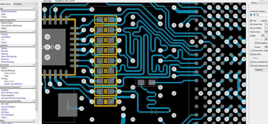
PCB Layers and Traces

The Oppo A3s PCB layout consists of multiple layers of conductive material that are stacked on top of each other. These layers are used to create the necessary connections between the different components of the phone.
The number of layers used in the Oppo A3s PCB layout varies depending on the complexity of the design. Generally, the more complex the design, the more layers are required. The Oppo A3s PCB layout typically consists of four to six layers.
Traces are the conductive pathways that connect the different components of the phone. These traces are created by etching away the excess copper from the PCB layers, leaving behind only the necessary pathways.
The width, thickness, and spacing of these traces are critical to the performance of the phone. The width and thickness of the traces determine the amount of current that can flow through them, while the spacing between the traces determines the amount of interference that can occur between them.
To ensure the best performance, Oppo uses high-quality materials and advanced manufacturing techniques to create the PCB layers and traces for the Oppo A3s. This attention to detail ensures that the phone performs at its best and provides a reliable user experience.
PCB Design Software and Tools
PCB design software and tools are essential for creating a high-quality PCB layout. There are many software options available in the market, and choosing the right one can be a daunting task. Some popular PCB design software and tools include:
Each of these software options has its own unique features and benefits. Altium Designer, for example, is known for its user-friendly interface and advanced design capabilities. Eagle PCB is a popular choice for hobbyists and small businesses due to its affordability and ease of use.
In addition to software, there are also various tools that are necessary for PCB design. Some of these tools include:
- Schematic capture tools
- PCB layout tools
- 3D modeling tools
- Gerber file viewers
Schematic capture tools are used to create a schematic diagram of the circuit. PCB layout tools are used to design the physical layout of the circuit board. 3D modeling tools allow designers to view and manipulate the 3D representation of the PCB. Gerber file viewers are used to view and verify the Gerber files before sending them to the manufacturer.
Overall, it is important to choose the right PCB design software and tools for the specific project requirements. With the right software and tools, designers can create a high-quality PCB layout that meets all the necessary specifications.
