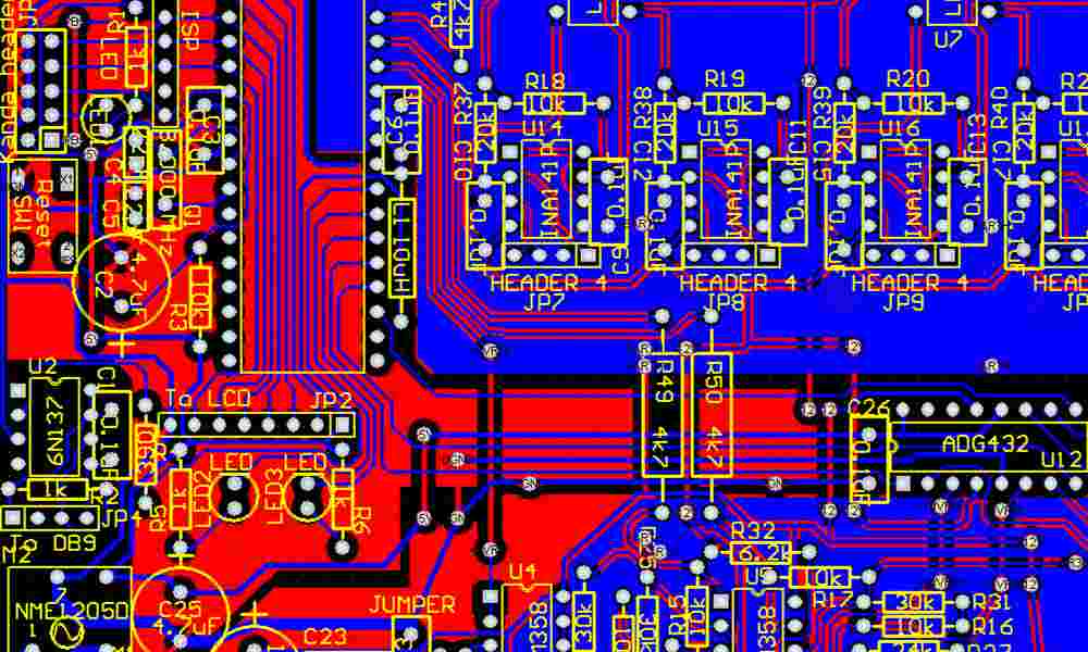
Designing a subwoofer can be a challenging task, but with the right knowledge and tools, it can be a rewarding experience. One of the most important aspects of a subwoofer design is the printed circuit board (PCB) layout. The PCB layout is crucial in ensuring that the subwoofer performs optimally and is reliable.
The PCB layout of a subwoofer is responsible for connecting all of the components together and providing a path for the electrical signals to flow. A well-designed PCB layout can help reduce noise and interference, improve signal integrity, and ensure that the subwoofer operates at its full potential. Additionally, a good PCB layout can help with troubleshooting and maintenance, making it easier to diagnose and fix any issues that may arise. In this article, we will explore some of the key considerations when designing a PCB layout for a subwoofer, including component placement, signal routing, and grounding.

PCB Layout Basics
PCB Design Software
When designing a PCB layout for a subwoofer, it’s important to choose the right software that can handle the complexity of the design. Some popular options include Eagle PCB Design, Altium Designer, and KiCad. These software programs offer a range of features, including schematic capture, PCB layout, and 3D visualization.
When choosing a PCB design software, it’s important to consider your budget, the complexity of your design, and the user-friendliness of the software. Some software programs may be more expensive but offer more advanced features, while others may be more affordable but have a steeper learning curve.
PCB Design Rules
PCB design rules are a set of guidelines that ensure the integrity and functionality of your PCB layout. These rules cover everything from trace width and spacing to via placement and component placement.
When designing a PCB layout for a subwoofer, it’s important to follow these rules to ensure that your design is reliable and functional. Some common PCB design rules include:
- Trace width: The width of the copper traces on your PCB should be based on the current that will flow through them.
- Trace spacing: The spacing between copper traces should be based on the voltage that will be present on them.
- Via placement: Vias should be placed strategically to ensure that they do not interfere with other components or traces.
- Component placement: Components should be placed in a way that minimizes noise and interference.
By following these PCB design rules, you can create a reliable and functional PCB layout for your subwoofer.
Subwoofer Circuit Design
Amplifier Selection
Selecting the right amplifier for your subwoofer is critical. The amplifier must be able to provide enough power to drive the subwoofer, but not so much power that it damages the subwoofer. The power rating of the amplifier should be equal to or slightly greater than the power handling capacity of the subwoofer.
When selecting an amplifier, consider the following factors:
- Power output: Make sure the amplifier can deliver enough power to the subwoofer.
- Impedance: The amplifier’s output impedance should match the subwoofer’s impedance.
- Signal-to-noise ratio: A high signal-to-noise ratio ensures the amplifier produces a clean signal.
- Distortion: Low distortion ensures the amplifier produces an accurate signal.
Filter Design
Subwoofers require a low-pass filter to prevent them from producing frequencies above their intended range. The filter should be designed to have a cutoff frequency slightly above the subwoofer’s lowest frequency response.
When designing a filter, consider the following factors:
- Cutoff frequency: The cutoff frequency should be set slightly above the subwoofer’s lowest frequency response.
- Slope: The filter’s slope should be steep enough to prevent unwanted frequencies from passing through.
- Phase: The filter’s phase response should be considered to ensure it does not cause any unwanted phase shifts.
In conclusion, selecting the right amplifier and designing an appropriate filter are essential steps in designing a subwoofer circuit. By considering the factors listed above, you can ensure that your subwoofer produces accurate, clean sound.
PCB Layout for Subwoofer

When designing a subwoofer PCB, it is important to consider the layout carefully to ensure optimal performance. The following sub-sections will discuss key considerations for PCB layout, including component placement, signal traces, and grounding techniques.
Component Placement
The placement of components on the PCB can have a significant impact on the performance of the subwoofer. It is important to place components in a way that minimizes noise and interference, while also ensuring that the circuit operates as intended.
When placing components, consider the following:
- Keep signal traces as short as possible
- Place decoupling capacitors close to the power supply pins of ICs
- Keep high-current traces and components away from low-level signal traces
- Place components in a logical and organized manner to facilitate troubleshooting and repairs
Signal Traces
Signal traces are the conductive paths that carry signals between components on the PCB. It is important to design signal traces carefully to minimize noise and interference, and to ensure that the circuit operates as intended.
When designing signal traces, consider the following:
- Keep signal traces as short as possible
- Use wide traces for high-current signals
- Keep signal traces away from high-current traces and components
- Use a ground plane to provide a low-impedance return path for signals
Grounding Techniques
Grounding is a critical consideration when designing a subwoofer PCB. Proper grounding can help to minimize noise and interference, while also improving the overall performance of the circuit.
When grounding a subwoofer PCB, consider the following:
- Use a ground plane to provide a low-impedance return path for signals
- Connect all grounds to a single point to minimize ground loops
- Place decoupling capacitors close to the power supply pins of ICs to provide a low-impedance path to ground
- Use star grounding to minimize noise and interference
By carefully considering component placement, signal traces, and grounding techniques, it is possible to design a subwoofer PCB that delivers optimal performance.

