Proteus is a powerful PCB design software that has gained popularity among engineers and hobbyists alike. It provides a comprehensive suite of tools for designing and simulating electronic circuits, making it an ideal choice for anyone looking to create high-quality PCBs.
One of the key features of Proteus is its ability to simulate circuits in real-time. This means that you can test your design before you even start building the actual PCB, saving you time and money in the long run. Additionally, Proteus comes with a vast library of components, making it easy to find the right part for your project.
Whether you are a beginner or an experienced engineer, Proteus can help you create professional-grade PCBs quickly and easily. In this article, we will explore some of the key features of Proteus and how to use them to design and simulate your own circuits.
What is PCB Design with Proteus?
PCB design with Proteus is the process of creating printed circuit board layouts using the Proteus software suite. Proteus is a popular software tool for designing and simulating electronic circuits. It is widely used by engineers and hobbyists alike for its intuitive interface and powerful simulation capabilities.
Proteus allows users to design and simulate complex electronic circuits with ease. The software includes a wide range of components such as resistors, capacitors, diodes, and transistors, which can be easily added to a circuit diagram using drag-and-drop functionality. Users can also create custom components and libraries to suit their specific needs.
Once the circuit diagram is complete, Proteus provides a range of simulation options to test the circuit’s performance. Users can simulate the circuit’s behavior under different conditions, such as varying voltage or temperature, to ensure that the circuit will function as expected in real-world scenarios.
Proteus also includes a powerful PCB design tool that allows users to create professional-quality printed circuit board layouts quickly and easily. The software provides a range of design features such as auto-routing, design rule checking, and 3D visualization, which help users to create accurate and efficient PCB layouts.
In summary, PCB design with Proteus is a powerful and intuitive process that allows users to design and simulate electronic circuits quickly and accurately. With its wide range of components, powerful simulation capabilities, and efficient PCB design tools, Proteus is an essential tool for any engineer or hobbyist involved in electronic circuit design.
Advantages of Using Proteus for PCB Design

Proteus is a popular software tool for designing printed circuit boards (PCBs). It provides a range of features and benefits that make it an excellent choice for PCB design. Here are some of the advantages of using Proteus for PCB design:
1. User-Friendly Interface
Proteus has a user-friendly interface that makes it easy to use for both novice and experienced PCB designers. Its interface is intuitive and well-organized, which reduces the learning curve and increases productivity.
2. Wide Range of Components
Proteus comes with a vast library of components, including microcontrollers, sensors, and other electronic components. This wide range of components makes it easy to design complex PCBs with ease.
3. Real-Time Simulation
Proteus provides real-time simulation of the designed circuit, which helps designers to identify and correct errors before the PCB is manufactured. This feature saves time and money, as it reduces the need for multiple iterations of the PCB design.
4. 3D Visualization
Proteus provides a 3D visualization of the PCB design, which helps designers to visualize the final product before it is manufactured. This feature allows designers to identify any potential issues with the physical layout of the PCB and make necessary adjustments.
5. Integration with Other Tools
Proteus integrates with other tools, such as microcontroller simulators and code generators, which makes it a complete solution for PCB design and development.
In conclusion, Proteus is an excellent software tool for PCB design, providing a user-friendly interface, a wide range of components, real-time simulation, 3D visualization, and integration with other tools. These features make it an ideal choice for both novice and experienced PCB designers.
Understanding Proteus Design Suite
Proteus Design Suite is a software package that allows you to design, simulate, and test printed circuit boards (PCBs). It is a comprehensive tool that includes schematic capture, PCB layout, and simulation capabilities. Proteus Design Suite is widely used by engineers and hobbyists alike because of its user-friendly interface and powerful features.
One of the key features of Proteus Design Suite is its ability to simulate circuits before they are built. This feature allows you to test your design and make sure that it works as intended before you spend time and money building the actual PCB. The simulation feature includes a wide range of analysis tools, such as transient analysis, AC analysis, and DC analysis.
Proteus Design Suite also includes a comprehensive library of components, which makes it easy to find the parts you need for your design. The library includes a wide range of components, such as resistors, capacitors, transistors, and ICs. You can also create your own custom components and add them to the library.
Another useful feature of Proteus Design Suite is its ability to generate 3D models of your PCB. This feature allows you to visualize your design in three dimensions, which can be helpful for detecting potential issues before you build the actual PCB.
In summary, Proteus Design Suite is a powerful software package that provides a comprehensive set of tools for designing and simulating PCBs. Its user-friendly interface, simulation capabilities, and extensive component library make it a popular choice among engineers and hobbyists alike.
Creating a New Project in Proteus
Proteus is a popular software tool for designing and simulating electronic circuits. In this section, we will discuss how to create a new project in Proteus.
To create a new project, follow these steps:
- Open Proteus software.
- Click on the “File” menu and select “New Project”.
- In the “New Project” dialog box, enter a name for your project and select a location to save it. You can also select the type of project you want to create, such as a schematic or PCB design.
- Click “OK” to create the project.
Once you have created your project, you can start designing your circuit by adding components, connecting them, and simulating the circuit. Proteus provides a wide range of components and libraries that you can use to design your circuit.
In addition to creating a new project, Proteus also allows you to import existing designs from other software tools such as Altium and Eagle. This can be useful if you have already designed your circuit in another software tool and want to simulate it in Proteus.
Overall, creating a new project in Proteus is a straightforward process that can be done in just a few steps. With Proteus, you can design and simulate complex electronic circuits with ease.
Designing Schematics in Proteus
Proteus is a powerful software tool for designing and simulating electronic circuits. One of its core features is the ability to create schematics, which are graphical representations of the components and connections that make up a circuit. In this section, we will explore the process of designing schematics in Proteus.
To begin, open Proteus and create a new schematic. You can do this by clicking on the “New Schematic” button in the toolbar or by selecting “File” > “New” > “Schematic” from the menu. Once you have a blank schematic open, you can start adding components.
Proteus includes a vast library of components, including resistors, capacitors, diodes, transistors, and more. To add a component to your schematic, simply click on the “P” button in the toolbar to open the component picker. From here, you can search for the component you want and drag it onto the schematic.
Once you have added your components, you can start connecting them together. To do this, select the “Wiring” tool from the toolbar and click on the pins of the components you want to connect. Proteus will automatically draw the wires between the pins, and you can adjust the routing as necessary.
Proteus also includes a range of tools for formatting and organizing your schematic. For example, you can use the “Group” tool to group components together and move them as a unit. You can also use the “Net” tool to label connections and highlight specific parts of the schematic.
In conclusion, designing schematics in Proteus is a straightforward process that can be accomplished with just a few clicks. With its extensive library of components and intuitive interface, Proteus is an excellent tool for both beginners and experienced designers alike.
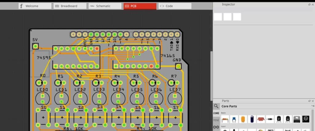
Creating PCB Layouts in Proteus
Proteus is a powerful software tool for electronic circuit design and simulation. One of its key features is the ability to create PCB layouts for your circuits. In this section, we will discuss how to create PCB layouts in Proteus.
The first step in creating a PCB layout is to design the schematic for your circuit. Once you have designed the schematic, you can use Proteus to generate a PCB layout from it. Proteus provides a range of powerful tools for creating PCB layouts, including automatic routing, manual routing, and a variety of design rule checks.
When creating a PCB layout in Proteus, it is important to keep a few key design principles in mind. First, you should ensure that all components are placed in an optimal location to minimize signal interference. Second, you should ensure that all traces are properly routed to minimize signal loss and interference. Third, you should ensure that all components are properly grounded to minimize noise and interference.
In addition to these design principles, Proteus provides a range of tools for optimizing your PCB layout. For example, you can use the autorouter to automatically route your traces, or you can use the manual router to manually route your traces. You can also use the design rule checks to ensure that your layout meets all necessary design criteria.
Overall, Proteus is an excellent tool for creating PCB layouts. Whether you are designing a simple circuit or a complex system, Proteus provides the tools you need to create a high-quality PCB layout that meets all necessary design criteria.
Simulating the Design in Proteus

After designing the PCB layout, the next step is to simulate the design in Proteus. Proteus is a powerful software tool that allows engineers to simulate and test their circuit designs before they are physically built. This can save time and money by identifying potential problems before they occur.
To simulate the design in Proteus, you will need to import the PCB layout file into the software. Proteus supports a wide range of file formats, including Gerber and Eagle PCB files. Once the file is imported, you can begin simulating the circuit.
Proteus provides a range of simulation tools, including virtual oscilloscopes, function generators, and logic analyzers. These tools allow you to test the functionality of your circuit and identify any potential issues. You can also use the simulation tools to optimize your design and make improvements.
One of the benefits of simulating the design in Proteus is that it allows you to test different scenarios and configurations. For example, you can simulate the circuit with different component values or test the circuit under different operating conditions. This can help you to identify the best design for your specific needs.
In conclusion, simulating the design in Proteus is an important step in the PCB design process. It allows engineers to test and optimize their designs before they are physically built, saving time and money. By using the simulation tools available in Proteus, engineers can identify potential issues and make improvements to their designs, resulting in better-performing circuits.
Exporting the Design from Proteus
Once you have completed your PCB design in Proteus, you will need to export it to a format that can be used for manufacturing or further design work. Proteus provides several options for exporting your design, including Gerber files, NC drill files, and bill of materials (BOM) reports.
To export your design, go to the “Output” menu and select “Export.” From there, you can choose the format you want to export your design to. Here are some of the most common options:
-
Gerber files: These are the standard files used for manufacturing PCBs. They contain all the information needed to create the copper traces, pads, and other features on the board. Proteus allows you to export Gerber files for the top and bottom layers, as well as any inner layers you may have used.
-
NC drill files: These files contain the information needed to drill the holes in your PCB. Proteus can export NC drill files in several formats, including Excellon and Sieb & Meyer.
-
BOM reports: These reports list all the components used in your design, along with their part numbers, quantities, and other important information. You can customize the format of the BOM report to meet your specific needs.
Once you have selected the format you want to export your design to, Proteus will generate the necessary files. You can then use these files to send your design to a PCB manufacturer or to continue working on it in another design tool.
It’s important to note that before exporting your design, you should double-check all the settings and configurations to ensure that everything is correct. This will help prevent any errors or issues during the manufacturing process.
In conclusion, exporting your PCB design from Proteus is a straightforward process that gives you a range of options for sharing your design with others. By following the steps outlined above, you can easily generate the files you need to take your design to the next level.
Common Issues and Troubleshooting Tips
Despite Proteus being a powerful tool for PCB design, issues can arise during the design process. Here are some common issues and troubleshooting tips to help you overcome them.
Issue: Incorrect Footprint
One of the most common issues that designers face is using the wrong footprint for a component. This can lead to a variety of problems, including incorrect pin connections, incorrect pad sizes, and incorrect spacing. To avoid this issue, always double-check the footprint before adding a component to your design.
Troubleshooting Tip: If you have already added the component to your design and realize that you have used the wrong footprint, you can easily replace it with the correct one. Simply right-click on the component and select “Edit Properties.” From there, you can select the correct footprint from the drop-down menu.
Issue: Design Rule Violations
Design rule violations can occur when the design rules are not set up correctly or when the design rules are too strict. This can result in errors such as overlapping pads, incorrect trace widths, and incorrect clearance between components.
Troubleshooting Tip: To avoid design rule violations, make sure that your design rules are set up correctly and that they are appropriate for your design. You can check for design rule violations by running a Design Rule Check (DRC). This will highlight any errors or warnings in your design and allow you to fix them before sending your design for manufacturing.
Issue: Incorrect Net Connections
Incorrect net connections can occur when traces are not properly connected to the correct pins on a component. This can result in a variety of issues, including incorrect functionality or even damage to the component.
Troubleshooting Tip: To avoid incorrect net connections, always double-check the connections between traces and pins before sending your design for manufacturing. You can also use the “Highlight Net” feature in Proteus to visualize the connections between traces and pins.
In conclusion, by being aware of these common issues and following the troubleshooting tips provided, you can ensure that your PCB design with Proteus is successful and error-free.
Conclusion

In conclusion, Proteus is a powerful tool for designing printed circuit boards. Its intuitive interface and extensive library of components make it easy to create complex designs quickly and efficiently.
One of the key advantages of using Proteus is its ability to simulate circuit behavior before the board is manufactured. This can save time and money by identifying potential issues early in the design process.
Another benefit of Proteus is its ability to integrate seamlessly with other software tools, such as schematic capture software and CAD tools. This allows for a more streamlined design process and greater flexibility in design choices.
Overall, Proteus is a valuable tool for any PCB designer, whether you are a beginner or an experienced professional. Its ease of use, extensive library of components, and powerful simulation capabilities make it an essential part of any designer’s toolkit.
