You may be wondering what rigid flex PCBs are, and that is why you are here. The rigid flex printed circuit board is a circuit board that makes use of the combination of the rigid as well as flexible board technologies in any application.
Also, they serve as a sure solution to the natural problems of product packaging. Often, people choose flex printed circuit boards because they are useful in solving problems that relate to getting the electronics in whatever products they serve. However, before we go into details concerning what they are, let’s first consider what the different types of flex circuits are.
What are the Types of Flexible PCBs?
Flexible PCBs can be classified into three:
Flex
The flexible printed circuit board (flexible PCB) describes a flex, which could feature polyimide stiffeners for the zif regions. However, the circuit in general is completely flexible
Flex having stiffener(s)
There may be cases where there is a need for some areas of the flex circuit to be rigid. To achieve this, polyimide or FR4 stiffeners could be added through pressure sensitive adhesive or lamination. In addition, the stiffeners are useful for the flex circuits having components on just one of the sides.
Rigid Flex
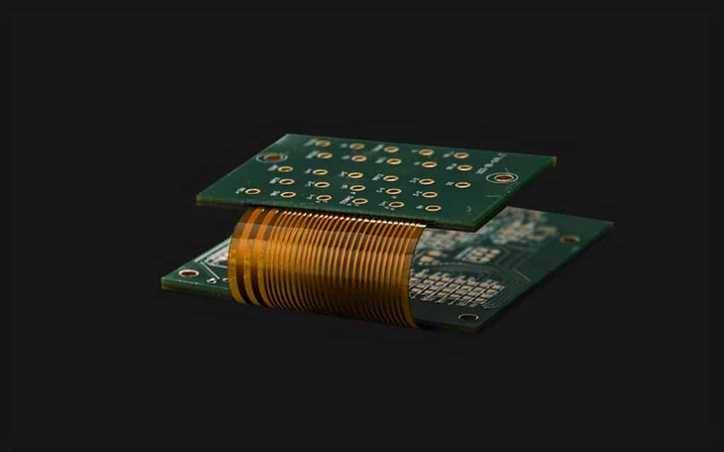
The rigid flex board combines both the features of the rigid board (rigid PCBs) and the flex circuit. These flexible layers are usually sandwiched in-between the two rigid boards making use of no flow prepreg. Note that this flex type functions effectively when components are present on the bottom and top sides.
Differences Between the Rigid and Flex Boards
The flexible PCBs (printed circuit boards) are different compared to the rigid boards
Material
Typically, the rigid boards are manufactured from glass epoxy compounds (FR4). The flexible circuits on the other hand, are manufactured from polyimide. However, there are some cases where rigid boards were created with polyimide. However, this is not common.
Coverlay
The flex PCBs (flex printed circuit boards may have a coverlay or flexible mask, while the rigid boards just make use of a solder mask. When you make use of a coverlay, the opening are either laser cut or routed. An adhesive is then used (about 1 or 2 mils) in adhering the coverlay onto the flex.
Stiffeners
The flexible PCBs usually make use of polyimide stiffeners or FR4 in stiffening some non-flexing regions. These stiffeners could be laminated onto the flex or it can be adhered making use of a pressure sensitive adhesive (PSA). However, the rigid boards on the other hand don’t require stiffeners.
Relative Permittivity
For the rigid board materials, they have a wide range for dielectric constants (relative permittivity). The flexible polyimide materials on the other hand is usually 3.4
For the purpose of this article, we will be focusing on the rigid flex PCB.
What is Rigid Flex PCB?
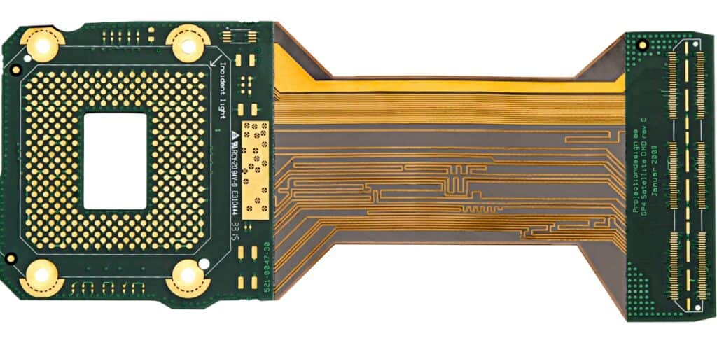
The rigid flex printed circuit board is a circuit board that makes use of the combination of both the rigid as well as flexible board technologies in any application. Furthermore, most rigid flex boards consist of many flexible circuit substrates attached onto at least one rigid board internally and/or externally.
This depends on the application’s design. In addition, the design of the flexible substrates make them to be in the flex state at all times. Also, during installation or manufacturing, they are formed in the flexed curve.
What are the Fabrication Applications of the Rigid Flex PCBs?
There are different applications of the rigid flex PCBs. This includes digital cameras, cell phones, smart devices, and more.
Increasingly, there has been a great use of rigid flex board fabrication in many medical devices like pacemakers. This is due to their weight and space reduction capabilities. In addition, you can apply these same benefits for rigid flex PCB usage which users can apply to the smart control systems.
For the consumer products, the rigid-flex doesn’t just help maximize weight and space, they greatly improve reliability, thereby getting rid of many uses for the solder joints as well as fragile, delicate, wiring which are prone to issues relating to connection. The above are just a few examples; however, the Rigid Flex PCBs are useful in benefitting almost all the advanced electrical applications, which includes automobiles, tools, and testing equipment.
The Production Process and Technology of Rigid Flex PCBs
Whether you are producing or manufacturing a rigid flex prototype or different production quantities that require large scale Rigid Flex PCBs assembly and fabrication, this technology is reliable and well proven. Also, this flex PCB portion does well in overcoming the space and weight issues.
Furthermore, you must consider Rigid-Flex solutions carefully and assess the available options properly at the beginning stages of the design phase of the rigid flex PCB will yield great benefits. In addition, this Rigid Flex PCB fabricator has to be involved very early during the process of design. This is to make sure that the both the fab and design portions are both in coordination and they account for the end and final variations of the product.
In addition, the manufacturing phase of the rigid flex pcb is also time consuming and more complex compared to the rigid board fabrication.
The entire flexible components of Rigid Flex assembly comes with a fully different etching, handling, as well as soldering processes in contrast to the rigid FR4 boards.
What are the Advantages of Rigid Flex PCBs?
Below are some of the advantages of using rigid flex PCBs
- You can minimize space requirements when you apply 3D
- Removing the importance of cables and connectors in-between these rigid parts, you can reduce the overall system weight and board size.
- When you maximize space, lower counts usually occur in parts.
- Lesser solder joints usually ensure higher reliability of connection reliability
- It is easier to handle during assembly in contrast to the flexible boards.
- There is a simplified process for PCB assembly
- ZIF contacts that are integrated offer to your system environment simple modular interfaces.
- Simplified test conditions. It becomes possible to conduct a full test before you go ahead with the installation.
- Assembly costs and logistical costs are well reduced when using the Rigid Flex boards.
- Also, you can increase the mechanical designs complexity. This also helps in improving degree of freedom for the different optimized housing solutions.
Why Should You Choose Rigid Flex Circuits?
Since their introduction, the rigid flex circuits and flexible circuits have steadily moved from the electronic interconnection fringe to find its place at its center. As of today, the rigid flex circuits and the flex circuits are seen in many products.
These products vary from very simple ones to the very complex ones. There are numerous reasons for this great shift to the middle or center, and majority of them can be linked to the great benefits they offer. Examining and explaining these benefits will make this clearer to you.
In addition, they are a reliable three dimensional solution, which permits the placing of operation/functional elements like connectors, displays, switches, etc) and electronic components in optimal locations in the product making sure the customer uses it with ease. Also, you can form and fold them around the edges, to help in fitting the required space to prevent the breaking of the assembly in discrete pieces.
Furthermore, they aid in reducing assembly costs. Before the broad utilization of the flexible circuits, the assemblies were known as a collection or combination of different connections and circuits. Also, this situation has caused the assembly, kitting, and purchasing of different parts. When you make use of a specific flex circuit design, there will be a reduction of the amount of part numbers necessary to make the circuit related interconnections to one.
Furthermore, they get rid of any possible human error. This is due to the fact that their design comes as the integrated circuit having the design artwork controlling the interconnections. With this, the possible human errors when making these interconnections are eliminated. Also, this is true for cases where interconnection is done using discrete wires.
Fabrication and Design Issues of the Rigid Flex Boards
When handling the PCB design, there are some considerations you must put in mind for the size variations of the final product. When manufacturing rigid flex boards, this flexible polyimide core shrinks immediately the etching away of the bonded copper foil happens. You have to account for this variation during the process of design.
Furthermore, the last stage in the assembly process needs the bending of the flex portions into shape. This stresses the flex laminations bringing about the possibility of causing stress fractures.
What is Rigid Flex Manufacturing?
During the manufacturing of rigid flex boards, you have to spend some engineering consideration. This has to do with ways of sectioning and releasing non-circuit areas in-between the flex and rigid sections. This design seeks a rigid section, which is made up of FR4 or any other type of rigid material, as well as a flex section which extends from inside the major circuit. It is also important to know ways in which these areas separate. Many methods like polyolefin release sheets or Teflon blocks allow the separation of the flex and rigid within that press package.
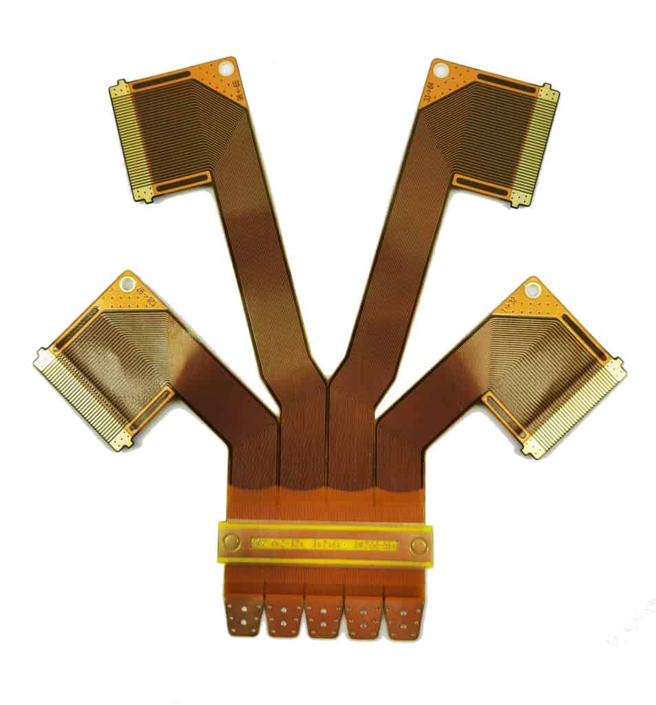
Let’s make use of a very simple example of a rigid flex with four layers and with a two sided flex core. These flex arms extending off this rigid board will not be able to adhere to the FR4 sheets that is found on the flex arms’ top layer
The pre-routing of the low-flow prepreg is done to cover just the FR4 board excluding the extension arms of the flex. To help in facilitating the last routing, a pre-routing is done on the FR4 with a slot present at a join line of the rigid and flex parts. After routing the board, the slot helps in facilitating the router from passing through or over the join area.
To help get rid of the topmost FR4 layer, you can score it alternately underside before you press.
Also, the inner layer of panels could feature some cut outs, which is filled with Teflon plug. This will allow the laminating press to deliver even pressure. However, it won’t stick to either the flex adhesive material or FR4 material.
More on Rigid Flex Manufacturing

The polyimide core usually bonds to the FR4 with adhesive sheets or prepreg. This offers a better high strength for the joint. Also, the expansion difference found between the rigid and flex sections has become an issue for registration. In addition, the manipulation of the CAD package is necessary. This helps in the scaling and aligning of the layers after pressing and processing.
Furthermore, there is a longer design time for the rigid flex. This is due to the fact that the engineering necessary to ensure the separation and correct alignment to the flex fingers that extends from the major board into the sub boards.
Also, the electroless plating, drilling process works with all the usual materials for the rigid flex. You will conduct a plasma etch cycle before to the electroless copper. This helps in preparing the hole.
Some problems may exist when trying to get a very smooth transition between rigid and flex. There are fabricators that seal the joint using a material for relieving strain. This helps to hide that joint cosmetically and add strength. While designing, speak with the board shop to help determine the most appropriate way that this board should be produced.
Normally, flex circuits are named as the inner two out of four layers. However, building the flex as the outer layer is possible. In the release sheet management and layup design, you have to find a solution to ways of milling out of unused inner section of the FR4
In addition, when the designs make use of the multiple unbonded flex arms arranged in parallel, the special separator sheets are necessary to ensure that the polyimide layers don’t adhere to themselves.
Conclusion
There has been great use of rigid flex PCB in many applications. Furthermore, our rigid flex PCB capabilities at Rayming PCB & Assembly are great. You can trust us to deliver high quality rigid flex printed circuit boards.
