Flex-rigid board have constantly evolved to keep up with the sophistication level and changing user requirements. For instance, today’s kind of user preference and sophistication levels are markedly different from that of the pre-computing age. The emergence of the Rigid flex PCB is a consequence of this evolution. It is a crucial high-performance and cost-effective electronic product solution compared to earlier wire-harness assemblies.
What is a Rigid Flex PCB?
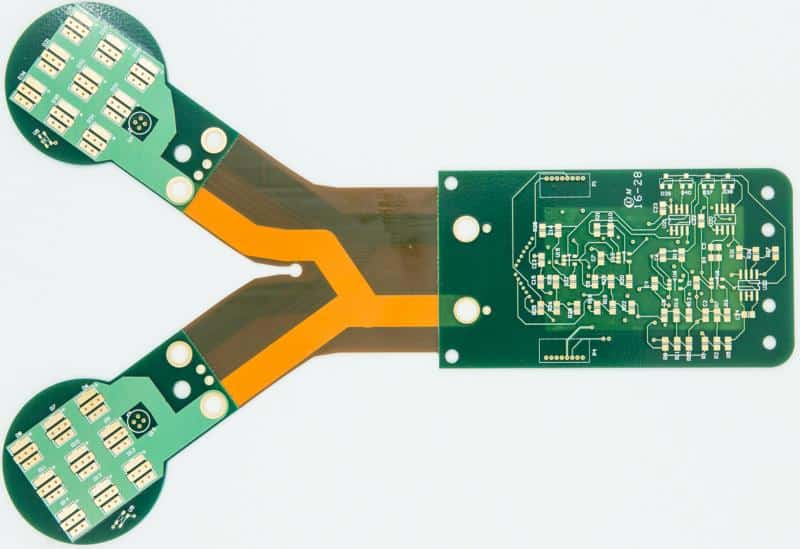
Wonderful rigid-flex pcb come as balanced hybrids of rigid and flexible circuits. It combines all the top features and benefits of either type of printed circuit board. For instance, flexibility adds to the benefits of rigid PCBs and ensures a more straightforward and precise maneuver of the PCB during the installation process.
Flex-rigid pcb have a manufacturing process that resembles the old-fashioned hardboard circuit. However, some of the circuit layers running through the board are flexible. Because of this, plated through-holes become vital connecting components between the rigid and flexible parts of the circuit.
Rigid Flex circuit boards are helpful for electronic devices. But beyond electronic devices, they have applications in the industrial and commercial sectors. It plays a fundamental role in high-grade weapon guidance systems, especially those mounted on aircraft, aerospace, and military electronic manufacturing.
The configuration of wonderful rigid-flex pcb allows for an assembly process that resembles that of a rigid pcb. In addition, it allows for folding when it comes to electronic products with space challenges. It is also ideal for constantly flexing applications. A proper rigid flexible pcb design withstands multiple flex cycles (hundreds of thousands) without failure. Additionally, the integrated unit of flexible and rigid substrates allows for any potential manipulation into 3D subassemblies.
Many people confuse flex-rigid pcb with a flex board possessing stiffeners. While similar sometimes when it comes to their applications, the two are different. Stiffeners can prove helpful in giving the flex circuit some stability during assembly and for mechanical purposes but ultimately come short when as they prove restrictive in component placing spots and the general component density. Therefore, the PCB designer needs to decide whether the stiffener will guarantee the required component density.
Designing a Rigid Flex PCB
The design process of a rigid-flexible pcb manufacturers is vital in determining the quality and functionality of the circuit post-deployment. Design considerations should always consider the fabrication cost, the fabricator’s capacity, intended application, material availability, etc. However, specific and fundamental factors such as layer count consideration, heat sinking, and comprehensive analysis of the PCB’s material layup needs consideration.
Why Such Considerations are Vital
Layer count consideration
A Rigid flex PCB is composed of alternating or interchanging layers of rigid and flexible PCB material. It becomes prudent to determine the number of layers needed for the PCB when transitioning from rigid to a wonderful rigid-flex pcb type. Always consult RayMing PCB and Assembly as your OEM (original electronic manufacturer) to ensure your requirements are within the fabrication confines handled by the company. It helps ensure that your OEM can manage the layer number in your rigid-flexible pcb when fabricating.
Heat sinking
Heat dissipation is a crucial aspect in rigid+flex , mainly when current flows through the electronic device. The total heat released is dependent on factors like power, device characteristics, and circuit board design. Whenever an increase in the amount of heat happens, the device’s performance gets affected, resulting in damage. It is therefore imperative to consider mitigating measures to limit the quantity of heat dissipation.
A critical method of ensuring this in your Rigid flex PCB design includes adhering to the rigid-flex design guidelines to ensure the PCB facilitates heat sinking. Considering such an aspect prevents overheating that, in turn, damages your rigid-flex board components.
Material layup
The layup of PCB materials is always vital for flex-rigid board. Getting the best possible material layup is crucial, which becomes a reality when closely collaborating with your Rigid flex PCB manufacturers. Some of the essential subjects of close collaboration revolve around the following.
- The rating regarding UL flammability
- Suitable materials
- The needed minimum bend radius
- Impedance control
- RoHS certification
- Compatibility when it comes to lead-free assembly
- Mechanical considerations
Material layup influences the performance, cost, and manufacturability. Therefore, it is prudent to dedicate sufficient resources and time to get the most befitting layup. You can kick-start the process by developing a befitting mock-up, getting a designer to compute the relevant calculations before verification by your fabricator.
It is also possible to utilize boards that have different layers. For example, you might have a board with twenty layers and another board with twelve. But having them have a similar layup becomes vital. Similarly, observing flex-rigid PCB design rules besides similar thickness is essential. It assists in reducing the manufacturing issues with the potential of derailing the projects.
Design Guidelines for Rigid-Flex Printed Circuit Boards

Plenty of differences exist between the rigid-flexible pcb, especially in Rigid flex PCB CAD design. It is therefore integral to consider the following guidelines in designing your semi flex pcb circuit boards.
Design needs for the flexible zone circuit
- It is prudent to avoid abrupt contraction or expansion of the line besides adopting the “tear shape” between thin and thick lines. Adopting rounded edges also becomes instrumental in circumventing sharp corners.
- Always take the supreme value whenever the pad satisfies the electrical needs. An even transition line is utilized to connect the conductor with the pad, which circumvents right angles. Incorporate the autonomous pad with a toe to help strengthen and provide the supporting effect.
Dimensional stability
Incorporate copper design in plenty. It is crucial to design a lot of compact copper ponds within the waste region.
The design of the cover film window
Incorporate the manual alignment holes for enhanced alignment accuracy. The window design takes into account the glue flow range. It is important to remember that the window opening comes larger compared to the initial setup. While the specific size gets provided (by ME design standard), the dense and small windows deploy unique mold designs (involving the jump punch, rotating punch, etc.)
Design of the transition zone
To ensure a smooth transition, it becomes instrumental in placing the line perpendicular to the bend direction. It is also important for the wires to get evenly distributed all over the bend area. The width of the wire needs maximizing, especially within the bend area. Additionally, avoiding the use of PTH design on the transition region is essential.
Design of the flexible region or zone with the requirement for air-gap
It is vital to avoid through holes on the anticipated bent area or part—incorporating the extra protection copper wires on either side of the lines. Whenever the space proves insufficient, select the best part’s inner R corner. For additional fortification of the copper wire, it becomes necessary to design the connecting part as an arc. You also have to ensure a larger bend area.
- It is essential to understand that the flexible board’s tool holes are impossible to share. It includes punch hole, SMT, ET, positioning hole, etc.
Rigid flex PCB Design Suggestions
Rigid+flexboards are product segmentation promoting field application and technical level of flexible circuits. It helps the system products to move towards a broader space. While the system miniaturizes the electronic product, it also solves plenty of in wiring and assembly. The design of immersion silver flex-rigid pcb features structural considerations as a critical factor. It is fundamental to ensure the process is simple, reliable, and of low cost. Therefore, before submitting your design to your preferred OEM, it is important to consider and crosscheck the following.
The checklist
- Reduced thickness and material types
- Reducing the thickness significantly as well as the types of the materials becomes necessary. A Rigid Flex circuit board with a significant thickness negatively affects the miniaturization efforts of the assembled electronic products. It thus leads to inconvenience during manufacturing (pressing). Further, the materials used, such as copper foil, acrylic glue, and polyimide film, influence the quality and ease of the process. Different materials can pose differential and considerable challenges when it comes to dimensional accuracy. Similarly, the enormous thermal expansion coefficient differences will influence the adhesion among layers post thermal shocks. Therefore, you need to pay some attention to these factors as well.
- Stress deterrence at the bending points. Besides the hot-pressing process, reducing stress on the edges of the flex and rigid parts of the board becomes necessary. It will provide extra reinforcement. One key way of going about it entails limiting the need for bend points. Some of the critical ways of ensuring stress deterrence include the following.
It’s essential to consider the shock resistance and folding resistance. The wiring deployment needs to meet the folding resistance. As a result, prior consideration proves pivotal whenever the product’s application involves a high-vibration setting or environment.
You can also pre-imagine the process considerations by anticipating potential problems and simplifying the process to mitigate these factors. Other factors can entail streamlining the process to increase yield and reduce costs.
Typical Structures in a Rigid Flex PCB
A Rigid Flex circuit board encompasses gluing of either one or extra rigid layers on a flexible board. Metallization connects the circuit between the flexible and rigid layers. It is common for every rigid-flex board to have rigid areas (one, two, or more) besides a flexible area or zone.
It can also encompass a combination of a single flex pcb with numerous rigid boards and numerous flexible boards and numerous rigid boards.
Rigid Flex circuit boards require electrical interconnection, which is achieved through drilling, laminating, and hole plating processes. Based on the requirement of the design, the concept of the design can prove more suitable for debugging and installing devices or for the welding operation. Regardless, the assembly installation often proves flexible.
Applications of Rigid Flex Circuit Boards
Industrial Application
Rigid Flex circuit boards under industrial application entail those for the military, medical, and industry sectors. It is possible because many industrial parts need safety, resistance to damage from the soil, and accuracy. Because of the importance of a Rigid flex PCB in such applications, it needs to be highly reliable, have a low impedance loss, high precision, durability, and have the quality of completing the signal transmission. But the output often proves small as a result of the complexity of the fabrication or manufacturing process. Such an output increases the unit price, which comes with prohibitive price tags.
Mobile phones
Rigid-flexible pcb apply in mobile phones, especially in the hone hinges of foldable smartphones, camera modules, radiofrequency and camera modules, etc.
Consumer electronic products
DV and DSC represent the Rigid flex PCB in consumer electronic products. It can imply and get discussed as a structure or in performance terms. Flexible and rigid boards are capable of connecting diverse circuit rigid boards beside components in 3D. Increasing the circuit carrying capacity and the overall usable area is always possible, especially under a similar circuit density. Further, you can reduce the contact limit of signal transmission besides reducing the assembly error rate. Conversely, the process of bending wires is simpler because Rigid flex pcb manufacturer is thinner and lighter. It is thus important to reduce the weight and volume.
Automotive
Semi flex PCB finds a standard application in automobiles and other areas in the automotive industry. It includes steering wheel buttons that link to the respective motherboard. In contrast, others include the video system screen to the control panel in cars, the function or audio keys’ operative connection on the car’s side door. It also involves the radar imaging system for reverse function, sensors (including temperature, air quality, specific gas regulations, and humidity). Rigid flexible pcb fabrication also apply to vehicles’ communication systems, rear-seat control systems, and vehicle detection systems, etc.
The Rigid Flex PCBs bypasses the assembly weight and size of electronic devices or products. It also helps in circumventing wiring errors besides enhancing the assembly’s flexibility. Rigid-flex also improves reliability and achieves 3D assembly in divergent assembly conditions. FPCs or Flexible Printed Circuits’ structure, lightweight, small size, and flexibility meet rigid PCB to ensure the 3D assembly needs are met. Interconnection technology is widespread and a highly valued tech in the electronic communication sector. The trend in recent periods has resulted in increased miniaturization of rigid-flex systems and electronics in general. It has encompassed the aspect of enhancing function and reducing the system’s volume.
Materials Attributes of Rigid Flex PCB
Materials always represent an essential aspect for consideration when designing printed circuit boards. The same applies with Rigid Flex PCBs, though understanding the type of PCB comes in handy for material selection. Rigid Flex PCBs have both the rigid circuit board aspects as well as the flexible circuit aspects.
Materials for Rigid-Flex PCB
Rigid Flex PCBs require different materials based on the functionality of the layers besides components. It includes the following.
Conductor. In most cases, a standard rigid PCB will have a copper layer for conducting electrical and electronic signals like data signals. However, for flex parts, it can also come as silver ink, aluminum, or carbon.
Insulator. Doubles up as the substrate and separates the electrical conductor parts from one another without conducting electricity. It gives the PCB structural support. It includes polyester, polyimide, polyethylene terephthalate, and solder mask for the flexible part. The rigid part comprises epoxy glass substrate or Teflon, or other relevant materials.
Adhesives. Adhesives are not necessary for Rigid Flex PCBs. However, if any need arises for attaching components on the flexible part, material such as epoxy, acrylic, or pressure-sensitive adhesives can apply. Additionally, most PCBs, especially the flexible ones, do not require adhesives because of the adhesive-less technology.
Finishes. It applies to Rigid Flex PCBs and safeguards the metallic surface from oxidation by preventing it from environmental exposure. It comes in diverse colors though it is green in most instances. However, the final finish depends on the application of the circuit. It is composed of solder, nickel, or gold, silver, or carbon immersions.
Rigid flex PCB Material Attributes
Dielectric Substrate (Consists mainly of polyester (PET) or Polyimide (PI))
Attributes of Polyimide (PI)
- Decent heat resistance. It has a lasting use temperature of 260℃ though it can endure high temperatures that go above 400℃.
- It has decent mechanical and electrical properties.
- A decent chemical and weather resistance
- It also possesses a proper flame retardancy
- Polyimide has a high rate of water absorption and thus makes the size change post-moisture absorption. It comes as an undesirable defect.
The rate of dimensional change always proves vital as an acceptance index. It thus needs consideration by IQC before polyimide material gets accepted for use in Rigid flex PCB fabrication. It also features stricter environmental control needs during production compared to rigid boards. Polyimide is popular and the most used between the two.
Attributes of Polyester
On the other hand, polyester has decent electrical and mechanical properties like water resistance, tensile strength, and dimensional solidity or stability post absorption of moisture. However, the polyester film possesses a tremendous shrinkage rate upon heating besides having poor resistance to heat. Additionally, it proves unsuitable for high-temperature soldering (lead-free soldering temp of 235 ℃ with a melting point of 250 ℃. However, this material is seldom used.
Cover Layer
It is instrumental in protecting the circuit, providing insulation, besides ensuring board deflection and electrical demand.
Attributes
It has decent electrical characteristics, decent process-ability, and excellent flexibility.
It is composed of polyimide, mostly 12.5mm/15mm/25mm/50mm/75mm/125mm
High thermal resistivity and flex life
The diverse categorization includes photo-imaging cover-coat, flexible solder mask, and other covering films and protective film materials.
Adhesive Sheet
Comprises of the bond-ply insulation layer
It has to get pressed at 190 ℃/85 (kg/cm2) pressure or a forming pressure of 60 seconds.
Conductive Layer
It comes as a rolled and annealed copper layer measuring 9mm/12mm/17.5mm/35mm/70mm.
Attributes
- High flex life with decent forming characteristics
- Electrodeposited copper of 17.5mm/35mm/70mm
- Silver In
- Extra cost
It is the most cost-effective, though with poor electrical attributes. It primarily gets used for shielding or in making connections among copper layers.
SF-PC5000 EWPF (Electromagnetic Wave Protective Film) Thickness Attributes
It totals a thickness of 22 microns—deploying the hot-melt technique to process the compound between the two films (insulating).
The outer insulating film or layer possesses an incredible wear resistance, while the inner film comes with extreme flexibility.
- Enhanced flexural performance and sliding performance
It possesses a superior sliding performance compared to silver paste and thus promotes thinning, especially for slide-type phones (smartphones)
- Adaptable to moisture-resistant soldering (reflow)
It has an enhanced insulating resin that ensures the realization of thinning besides improving the gas penetration capacity.
- Decent dimensional stability
Aspects such as the insulating resin’s rate of thermal shrinkage are less compared to earlier materials. For instance, it only ranks one-tenth of early or original material.
Extra Materials and Stiffeners
The tough material also gets pressed on the soft board’s local area for incorporating reinforcements or welding parts for installation.
Low or No Flow PP
It comes very thin and is used for laminating rigid-flexible boards. It includes 2mil, 3.0mil / 3.5mil, and 5.6mil w/o micro-via.
Benefits of Rigid Flex PCB
Rigid Flex PCBs have a myriad of benefits for both the electronic product consumer and the manufacturing company. Some of these benefits include the following.
- Mechanical stability. The basic structure of Rigid Flex PCBs comprises interchanging flexible and rigid layers. It ensures flexibility and stability of both layers, which facilitates simple installation in small spaces.
- Reliable connection. It offers greater polarity and stability, making connections more straightforward and extra secure with other parts or components. It also needs fewer connector parts with every application.
- Together with precision and repeatability, it offers better packaging flexibility.
- Cost-effective. It allows you to cut on the overall expenditure by utilizing Rigid Flex PCBs.
- High-density applications. It is instrumental for the high-density device population due to its stability, space-friendly attribute, and flexibility.
- High vibration and shock. The resistance to vibrations and shock allows for its utilization in a broad range of electronic components. It includes those operating in harsh conditions (vibrations and shock) without any damages.
Final Thoughts
Plenty of benefits accrue from using a Rigid Flex PCB. As a result, understanding the diverse elements, including its design, structures, materials, and fabrication, becomes pivotal. If you wanted to have a better comprehension about the design of Rigid Flex PCBs, then we hope you are better for it at this point.
