Printed circuit boards, or PCBs, have excelled in various applications. Traditionally, most printed circuit boards were built using through-hole technology (THT). However, after the development of Surface Mount Technology (SMT) and surface mount devices, it has taken over the THT assembly process for many reasons.
Surface-mounted technology and THT both have pros and cons, and how a circuit board is mounted determines how it works. With that said, through-hole mounting technology involves attaching components with leads on a printed circuit board using plated-through holes.
Do you want to know THT’s components, advantages, and disadvantages in depth? Then keep reading, because we’ll tell you some secrets about through-hole mounting technology.
What Is Through-Hole Technology?
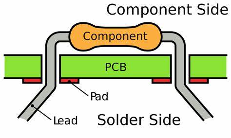
Components using through-hole technology have their tails or leads inserted into pre-drilled holes in the printed circuit board. After that, using a technique known as the wave soldering process, the leads can be affixed to the pads or land on the bottom of the circuit board.
This method recently transitioned from a simple borehole to a plated through hole. The lead is then inserted via a hole filled with solder paste.
This process, known as the pin-in-paste wave soldering process, involves heating the entire PCB assembly to reflow the solder paste.
Since both component types may be soldered during a single process, this innovation enables boards that contain both through-hole and surface-mount components.
Because THT mounting produces solid mechanical bonding and is a tried and true procedure, it is very trustworthy. Fewer variables than surface mount may result in soldering problems, and these factors are often well-researched and understood.
THT Printed Circuit Board Technologies
For the design of multi-layer PCBs, through holes are a crucial component. However, through-hole mounting technology is more expensive and less dependable than surface-mount technology since it is not automated and relies on the expertise of the operators.
Leads are first trimmed to the proper size for printed circuits before the THT components are inserted. However, some components must be placed at a certain distance from the board.
Then the components are set at the proper height using “spacers” made of metal or plastic. For securing the spacers, you need to do soldering, screwing, and snap-fitting.
THT components are made up of 3 components:
- A pad
- A via
- An isolation area of the power plane
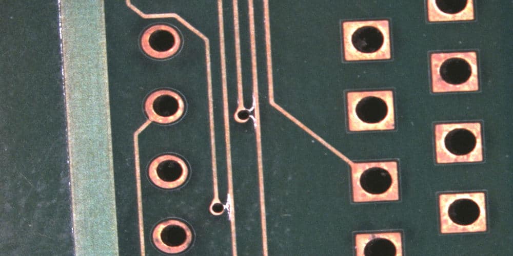
A metal layer is plated onto the hole walls via chemical deposition to obtain THT. This allows the copper foil on the circuit board’s inner layers and planes to line with one another electrically. Then using a tracing on th top and bottom layers, two through-holes are created on opposite sides of a regular pad.
These through-holes can be connected directly or left unconnected. Whereas a through-hole is used to position, fix, and connect electrical components.
In the meanwhile, THT components can be divided into three types:
- Blind throughs
- Buried through
- Though-hole vias
Most PCBs use through-hole vias extensively since they are widely available and inexpensively priced in technology. It involves a hole drilled through a circuit board’s layers, which are either used for an internal connection on a positioning feature.
Whereas blind via is the term used to describe the hole that connects internal traces below surface traces at a specific depth. And “buried via” is used to describe a connecting via that is positioned in an internal layer.
Applications of THT Electronic Components

Following are the application of THT electronic components assembly:
High-Voltage Areas
These THT devices are used in medical devices. Therefore, a through-hole mounting electronic component is crucial because it offers a sturdy joint.
High-Stress Mechanical Devices
high mechanical stress devices, as in military hardware. High stress calls for robust joints to prevent breaks. Therefore, only the THT mounting can provide this assembly.
High Power Zones
Like steam boilers. Magnetic and Vibration forces accompany high power. For such devices, a through-hole mounting style is suitable.
Gadgets That Operate at High Temperatures
Like in nuclear power reactors. High reliability may be possible at high temperatures. As a result, we can employ THT because repairing damaged parts is simple.
Types of THT Components
Now that you know what THT mounting is and its applications, it’s time to discuss the types of THT components.
There are 2 types of through-hole components, axial leads components and radial leads components. Let’s discuss each of them briefly.
Axial Leads Components
Axial lead electronic components are the ones that are assembled using the THT procedures most frequently. In this instance, leads are visible from the sides compared to radial lead components.
Additionally, it can be divided into vertical mounting and horizontal mounting:
In vertical mounting, soldering is done on both sides of the board, allowing for the creation of strong mechanical joints. However, vertical mounting is a lengthy process.
In contrast, the mounting is bent to achieve the desired horizontal fixation due to its lengthy one-sided design. However, as soldering is possible on both sides of the board, horizontal mounting provides a sturdy mechanical connection.
Radial Leads Components
In radial leads components, the two leads come from the components’ common side. This type of THT mounting is commonly used in the packaging of capacitors.
Similarly, you can mount radial leads both vertically and horizontally.
In vertical mounting, the base is positioned parallel to the board.
In horizontal mounting, the position of the contact is in the horizontal plane. This allows the leads to have excellent bend and spacing.
Also, this enables the solder to be filled properly on the components resulting in the strongest components. Due to its secure mounting on the board, the component is immune from the effects of vibrations.
Advantages of Through-Hole Technology
- THT is far more dependable than surface mount technology because there is a much stronger bond between the components and the PCD.
- The majority of connectors still use THM.
- THM, is widely utilized in military applications and those that put a PCB assembly under a lot of strain or require rapid acceleration.
- In comparison to surface mount technology, prototyping and testing are substantially simpler with Through-Hole Technology.
Disadvantages of Through-Hole Technology
- In comparison to components that are surface mounted, through-hole components occupy a lot of area on a PCB assembly.
- The majority of through-hole components installed require manual placement.
Conclusion
The best way to manufacture huge PCB assembly boards is through THT mounting. It is the best for mounting mechanically robust components and the least expensive for testing and prototyping.
The method must be automated in order to match the speeds required for the creation of SMT components, and researchers are currently working nonstop to make this happen. THT could quickly replace surface mount device and SMT technology if that goal is met.
Numerous THT designs have already been automated, including the drilling of holes carried out by a machine and the soldering procedure.
So, if you’re also looking for an inexpensive method to produce PCB assembly boards, THT mounting technology is your to go.
