There is a widespread failure to appreciate the bearing of technological advancement on human existence. Recapping recent history may help put today’s technological advances into context.
Universal Serial Bus is an example of such technological development. The USB world is a wide-open field of interfaces. The problems of data transmission, file sharing, and media/software distribution have all been eased as a result.
Plus, it’s a hub for all your USB-enabled computers, electronics, and communications devices. In the course of time, it has become a standard in many electronic devices.
Connectors, of which there is a great variety, are often utilized in PCB construction. They serve as a visual representation of the transformation of data received through power relays into new products.
There are male and female versions of these user interfaces. Read on if you’re wondering how modern technology has improved our everyday lives. This article will discuss many different aspects of USB PCBs, including USB c PCBs, USB PCB Connectors, and USB circuit boards.
What is a PCB USB?
The abbreviation “USB” stands for “Universal Serial Bus.” This device can be plugged in and acts as an interface between PCB and its subsidiary setups.
Its dominance in the worldwide technical community has grown immensely over the years. It is essential both in terms of its continued relevance and the contribution it contributes to the economy of the world today.
It can do its job without any external components, and you don’t even have to charge it up before using it. Because of how well it works, transferring cases involving documents among companies and other institutions is now much less complicated.
PCB USB is a widespread sort of connection that may be encountered in numerous electrical items. They include laptops, phones, printers, pen drives, and several other electronic gadgets.
This aids in building rapport with possible infiltrators. Additionally, the USB connection strip is attached to the PCB so that the two may communicate with one another. Using the accessible USB port, this may be done easily.
The computer and various other electronic devices may connect with one another via the usage of a USB port. Digital information may be sent via wires thanks to the connector’s compatibility with USB devices.
In addition, the cable carries electricity to all the gadgets that need it. There are two basic sorts of PCB USB connections: wired and wireless. The two types of USB connections are known as wired and wireless.
The wired variant uses a cable and USB ports, while the wireless variety uses radio frequency. Typical usage for a PCB USB device is only the tip of the iceberg of what can be done with them. The following scenarios benefit from its use:
Locking and unlocking computer systems. As a result, it is useful for collecting the files together, thanks to the method of saving duplicate folders in a computerized manner for later use.
If you want quick access to folders and reliable data transfer capabilities, a USB flash drive is a great option for programs operating while connected to a wireless network.
Micro USB PCB Connectors
The micro USB PCB was designed to be a more portable version of the standard USB connection. It has a USB micro-footmark and drastically reduces the PCB size of many practical devices.
Most old Mini USB power outlets and receptacles have replaced the newer Micro USB PCB. The layout is mobile-friendly and even works with the latest USB on-the-go technology! Smaller devices abound, all capable of independent, host-free communication with one another (PC).
For linking up with the PCB, a micro USB connection is used. The tiniest cables now on the market are mini USB ones. It has two separate connections and a USB 3.0 port. It’s practical to connect several electronics to share a single power supply.
In addition, small USB cables are convenient add-ons that may be used in place of Mini USB link-up ports in gadgets when doing so saves on power or valuable real estate. USB cables act in ways that are consistent with the behavior of a standard USB cable.
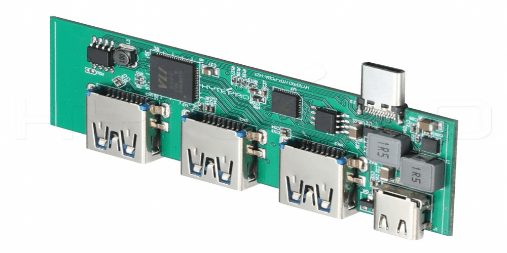
USB PCB Board
Because of its widespread use, a USB printed circuit board (PCB) is the heart of every device that employs the USB standard as its interface. Communication is greatly aided by modern technology, which allows for faster and more precise transmission of data.
Several USB 2.0 manufacturers have entered the market; however, you may have trouble using them. The USB designs provide several challenging difficulties during PCB assembly.
During PCB fabrication and assembly, 2.0 USB support must be ensured. In order to send a signal across several lines, like D+ and C+, as shown in the USB Compactness standard. In order for a device’s usefulness to be maximized, it has to have a unique line design that follows specific guidelines.
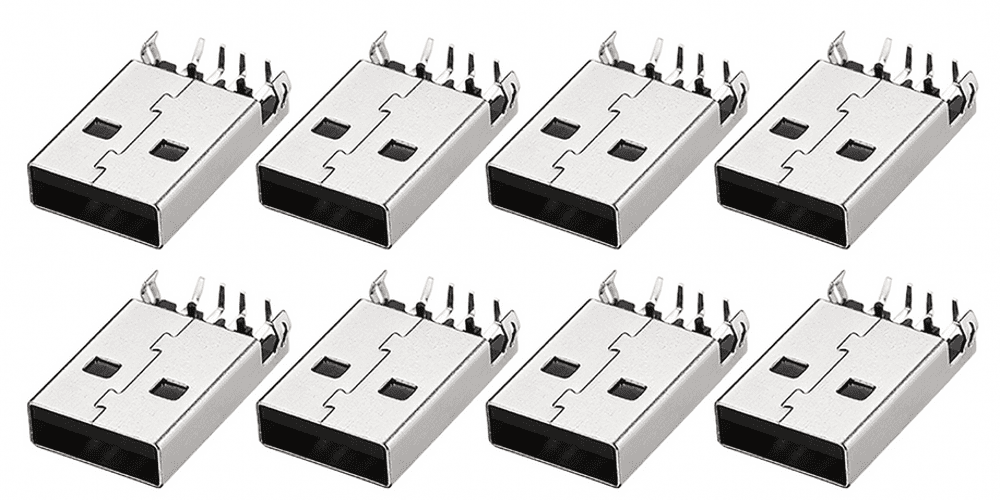
USB PCB Connector
It was a pain to hook up computers and other equipment back then. Connecting computers and peripherals through parallel and serial connections allow for data transfer. All of your peripherals—mouse, printer, keyboard, and gamepad—have their very own jack, but accelerator cards and software are required for connectivity.
As time progressed, newer and better technologies eventually replaced this temporary setback. The end outcome was a USB port. As a result, time spent on digital tasks and those using computers became more productive. Since it could simply be plugged in and played, it quickly became the standard. USB-printed circuit boards are split into the host and peripheral halves. To achieve production objectives, they share comparable component designs.
PCB USB Design Components
The following is a list of what goes into making a USB PCB.
- Shielding is a crucial part of the USB PCB’s design because it reduces the likelihood of interference. It prevents the signal part from being damaged by the electrical noise. The connection may be harmed if exposed for too long to a loud setting.
- The USB port may be utilized to provide electricity during setup. It guarantees a reliable connection. Data cables aren’t required for the connection. The USB won’t be harmed if the device’s power cord is attached to the data lines.
- Connector polarity is supported. Typically, there is just one feasible orientation, which implies that improperly placed connections may cause harm to electronic devices.
- The strain relief is quite important since it helps to relieve pressure on the connection. The strain on the USB connection might cause the signal to become garbled. Thus, a plastic sheath must be added to protect it.
- There must be at least four wires for the USB standard to be met. For instance, there are two and no more than five contacts in a USB 3.0+ connection. These terminals serve as the points of contact for the system’s power, D+ and D- data, and ground connections. A USB connection can only handle up to 500mA at 5V.
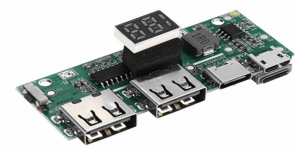
Types of USB PCB Connectors You Can Choose From
A variety of USB connections are available for a wide range of applications. USB connections are the most popular choice for PCBs with vertical mounting orientation. You can simply drill holes and then solder on the vertical plug.
This connection is the way to go if you need to attach a cradle. A variety of electronic devices and computers can be charged using them. The plugs and connections are horizontal versions of the standard plugs and sockets used in vertical orientations. Still, before being attached to the PC, the connections must be threaded through the plated drill holes.
The Vertical through Hole Connectors
These strains of PCB are female. They are manufactured in 3, 2, and 4 rows with a 0.050 specific contact gap and are made of staged plastic. These plugs are oriented vertically, like a spigot on a wall mount.
In addition, the PCBs covered through holes serve as a barrier for the stoppage before it is fixed. The vertical through-hole connection has a narrow profile, making it ideal for use in tight quarters.
Top Mount Connectors
The break-off lead is used to tie these sorts of connecting strips into place on the top layer of the PCB. It is most effective for mechanical equipment that is open to the risk associated with vibration and falling items.
Connectors that Attach in the Middle
The PCB location of the mid-mount connection is indicated by its name, and types like these are what low-key consumers need to satisfy their electrical wants and needs. They are a convenient solution if the PCB’s base height is an issue.
Connectors That Fit Into The Ground
All of these plugs are located on the PCB’s bottom. The connections between the applications that span the PCB can unite two boards side by side. There is a relationship between the holes in the base surface design and the header pins.
USB C. PCB
Many firsts and global firsts may be traced back to the widespread adoption of the USB. All walks of life may benefit from the technological advancements it has brought forth. In light of the rapid pace at which technology develops, it is crucial that outdated links be routinely upgraded.
As more and more modern devices are equipped with USB ports, upgrading these ports will soon be necessary. Some examples of such obstacles are the very large size and internal sound restriction of the standard A and standard B USBs.
A new USB C PCB specification was designed to accommodate changing device needs without compromising the functional advantages of earlier standards. For many years, electronic devices have used the USB-C PCB design for their connections. They can both transfer data and power at the same time.
It has improved spinning speed and ease over previous designs without sacrificing overturning capacity. Most USB-C connections can provide 2.5 watts of electricity and are smaller in size.
The following describes the quality requirements for the USB C PCB socket, power cord, and electrical outlet:
- Existing anchors and devices can have an agent set up where dimensions and aesthetic preferences are considered.
- Facilitating the linking of USB devices with the purpose of decreasing the number of required connections.
- Maintaining the current USB connection is not an issue for it.
USB Circuit Board
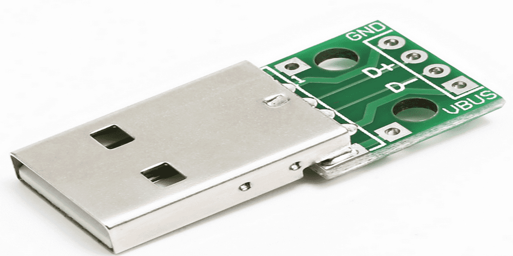
The Universal Serial Bus (USB) standard is recognized as a reliable method of connecting electronic devices to personal computers. It can link up with a computer and other gadgets (peripherals). There are four cables that connect it to your body.
A cable’s pins represent electrical connections, and the V BUS pin provides energy to other electronics. It gets its +5v power supply from the USB host. Pin D- is the ground for data (DM). Third lug to the left of D- (DM). Information may be sent via this protocol, which is also known as D+ (DM). Pin 4 is where everything starts, literally. (GND).
A layer of level dielectric material protects the circuit board, and copper shields the integrated circuit on either the outside or the inside. There may be two or more coated layers on the board. There are several challenges inherent in developing a USB-PCB layout. Accurately connecting the USB interface is necessary for optimal performance. Major challenges include power, arrangement, and interference. Errors in the layout lead to confusion and, eventually, a split.
USB Design Challenges
- Error-free USB circuit boards require preventative actions.
- DM and display port must fill the same gap for a signal-probable USB board. Differences in pin coverage affect signal timings. Data inaccuracy is inevitable. It’s crucial to examine the data trace’s distance and range.
- Another problem is alternating current resistance. To decrease wave reflection, the PCB’s DP and DM must match. PCB setup software may combine DM and DP signals. The design should be compact.
- Proper care prevents stubs. Producers add the stub while assembling base current diodes. It weakens data waves. DM and DP signals should always use the USB ground plane. This reduces the probability of DM and DP splits.
- USB connection design requires an appropriate power arrangement. So, manufacturers must consider how to power the USB IC.
Conclusion
USB PCBs are a crucial component. They play an essential role in creating cutting-edge electronics. Therefore, they provide the digital and electronic worlds with a boost in productivity, reliability, and creativity. Nonetheless, this article has illuminated several challenges and viable techniques for designing a successful USB PCB.
