Altium Designer is a popular software tool used by electronic design engineers to create printed circuit boards (PCBs). One of the key features of Altium Designer is its 3D view functionality, which allows designers to visualize their PCB designs in three dimensions. This feature has become increasingly important in recent years as electronic devices have become more complex and compact.
The 3D view in Altium Designer provides a number of benefits to designers. For example, it allows them to identify potential design issues early in the process, such as components that may be too close together or that may interfere with each other. This can help to reduce the number of design iterations required and ultimately save time and money. Additionally, the 3D view can help to improve communication between designers and other stakeholders, such as manufacturers and customers, by providing a more realistic representation of the final product.
Overview of 3D View in Altium
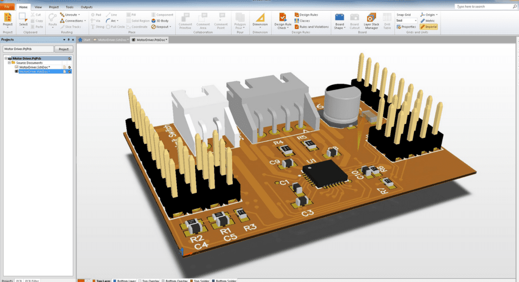
Altium is a powerful PCB design software that offers a 3D view of the PCB design. This feature provides a visual representation of the PCB design, allowing designers to see how the components fit together and interact with each other.
The 3D view in Altium is a great tool for designers who want to ensure that their design is free of errors and that all components fit properly on the board. It also helps designers to visualize the final product, making it easier to communicate design ideas with clients and stakeholders.
The 3D view in Altium is easy to use and can be accessed from the PCB editor. Once the 3D view is enabled, the designer can rotate and zoom in and out of the design to get a better view of the components and the overall layout.
In addition to providing a visual representation of the design, the 3D view in Altium also allows designers to perform collision detection. This feature helps designers to identify any potential issues with the placement of components and helps to ensure that the design is free of errors.
Overall, the 3D view in Altium is a powerful tool that can help designers to create accurate and error-free PCB designs. By providing a visual representation of the design, designers can ensure that all components fit properly and that the final product meets the requirements of the client.
Setting up the 3D View
Enabling 3D View in Altium
Before you can begin using 3D View in Altium, you will need to ensure that it is enabled. To do this, follow these simple steps:
- Open the PCB design file in Altium.
- Click on the View tab in the top menu bar.
- Select the 3D Layout Mode option from the dropdown menu.
With 3D Layout Mode enabled, you will now be able to view your design in 3D.
Configuring the 3D View Settings
Once you have enabled 3D Layout Mode, you can begin configuring the 3D View settings to suit your needs. To do this, follow these steps:
- Click on the View Configuration button in the top toolbar.
- In the View Configuration dialog box, select the 3D View tab.
- Here, you can adjust various settings such as the background color, lighting, and shadows to create the desired 3D View of your design.
When configuring the 3D View settings, it is important to keep in mind the purpose of the 3D View. For example, if you are using the 3D View to check for interference between components, it may be helpful to adjust the lighting and shadow settings to clearly highlight any overlapping components.
Overall, setting up the 3D View in Altium is a straightforward process that can greatly enhance your design workflow. With the ability to view your design in 3D, you can better visualize and analyze your PCB layout, leading to a more efficient and accurate design process.
Navigating the 3D View
Using the Mouse
The 3D view in Altium allows you to visualize your PCB design in three dimensions. You can use the mouse to navigate the 3D view and explore your design from different angles.
To rotate the view, click and hold the left mouse button while moving the mouse. To pan the view, click and hold the middle mouse button while moving the mouse. To zoom in and out, use the scroll wheel on your mouse.
You can also use the mouse to select objects in the 3D view. Click on an object to select it, and then use the Properties panel to view and edit its properties.
Using the Keyboard
In addition to using the mouse, you can also use the keyboard to navigate the 3D view in Altium. The following keyboard shortcuts are available:
- Ctrl + Shift + Left Mouse Button: Rotate the view around the X and Y axes
- Ctrl + Shift + Middle Mouse Button: Pan the view
- Ctrl + Shift + Right Mouse Button: Zoom in and out
- Ctrl + Alt + Left Mouse Button: Select an object and display its properties in the Properties panel
You can also use the arrow keys to rotate the view around the X and Y axes, and the Page Up and Page Down keys to zoom in and out.
Keep in mind that the 3D view in Altium is just a visualization tool, and any changes you make in the 3D view will not affect your actual PCB design. Use the 3D view to get a better understanding of how your design will look in the real world, and make any necessary changes in the 2D view.
Working with Components in 3D View
Selecting Components
When working with components in 3D view, it is important to select them accurately. This can be done by either clicking on the component in the 3D view or selecting it in the PCB layout. Once selected, the component will be highlighted in the 3D view and can be manipulated.
Moving Components
Moving components in 3D view is similar to moving them in the PCB layout. Simply click on the component and drag it to the desired location. This can be useful for checking clearances and ensuring that components fit properly in the enclosure.
Rotating Components
Rotating components in 3D view can be done by clicking on the Rotate button in the toolbar or by using the shortcut keys. The component can then be rotated in any direction, allowing for a more detailed view of the component and its placement on the PCB.
Overall, working with components in 3D view can be a useful tool for checking clearances and ensuring proper placement on the PCB. By using the selection, move, and rotate functions, designers can get a more detailed view of their design and make any necessary adjustments.
Customizing the 3D View

Changing the Background Color
One of the easiest ways to customize the 3D view in Altium is to change the background color. This can be done by going to the View Configuration panel and selecting the “Display” tab. From there, you can choose a new color for the background and see the changes in real-time.
Applying Materials and Textures
Another way to customize the 3D view is to apply materials and textures to the components in your design. This can be done by selecting a component in the PCB editor and going to the Properties panel. From there, you can choose a material and texture for the component, which will be reflected in the 3D view.
Adding Lights
Adding lights to the 3D view can help you to better visualize your design and make it easier to spot potential issues. This can be done by going to the View Configuration panel and selecting the “Lights” tab. From there, you can add and adjust the position and intensity of the lights in the 3D view.
Overall, customizing the 3D view in Altium is a simple and effective way to improve your design workflow and ensure that your PCBs are of the highest quality. By changing the background color, applying materials and textures, and adding lights, you can create a 3D view that is tailored to your specific needs and preferences.
Exporting 3D Models
Exporting to STEP or IGES Format
To export a 3D model in Altium, you can use the STEP or IGES format. This allows you to import the model into other software programs for further analysis or modification. To export a 3D model to either format, follow these steps:
- Open the PCB document in Altium.
- Click on the “File” menu and select “Export.”
- Choose either “STEP” or “IGES” from the list of available formats.
- Select the desired options for the export, such as the units and the level of detail.
- Click “Export” to save the 3D model in the chosen format.
Exporting to 3D PDF Format
Another option for exporting a 3D model in Altium is to use the 3D PDF format. This allows you to create a 3D model that can be viewed and manipulated in Adobe Acrobat Reader. To export a 3D model to the 3D PDF format, follow these steps:
- Open the PCB document in Altium.
- Click on the “File” menu and select “Export.”
- Choose “3D PDF” from the list of available formats.
- Select the desired options for the export, such as the units and the level of detail.
- Click “Export” to save the 3D model in the 3D PDF format.
Exporting to Other Formats
Altium also supports exporting 3D models to other formats, such as VRML and OBJ. These formats are commonly used in 3D printing and other applications. To export a 3D model to another format, follow these steps:
- Open the PCB document in Altium.
- Click on the “File” menu and select “Export.”
- Choose the desired format from the list of available options.
- Select the desired options for the export, such as the units and the level of detail.
- Click “Export” to save the 3D model in the chosen format.
Overall, exporting 3D models in Altium is a straightforward process that allows you to create high-quality models for use in other software programs and applications.
