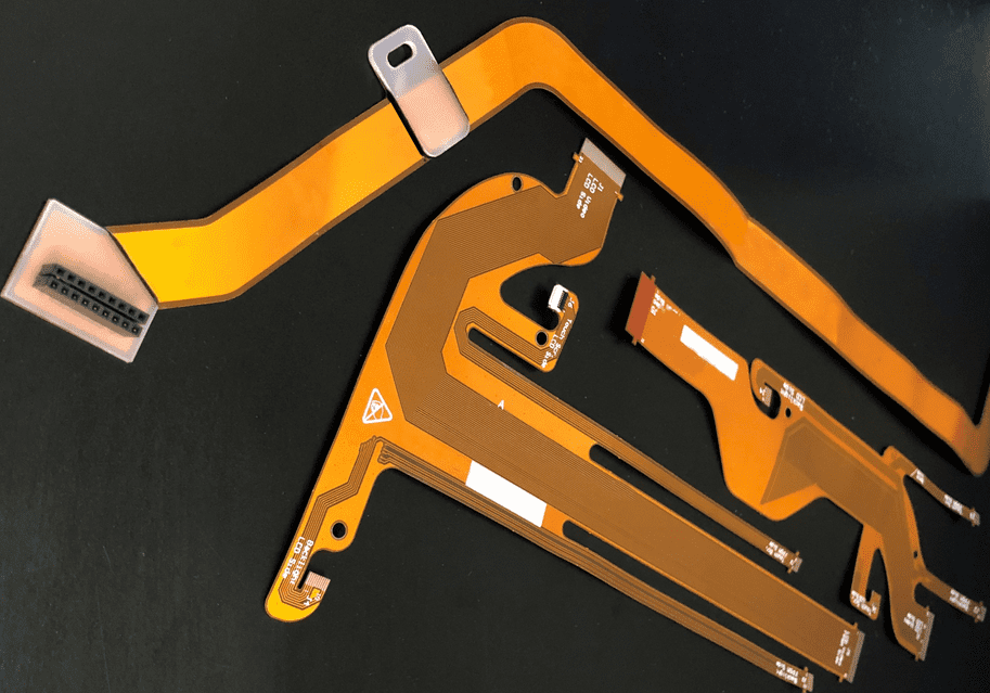
The term flexible PCBs is identical to Flex PCBs. These circuits have the ability to fit with any design of electronic devices or other kinds of products.
These circuits are for the special functioning of electronics. These also have a unique arrangement of circuit parts, unlike other PCBs. The base material used in flex PCBs is amenable as well.
Major Advantages of Flexible circuits prototype
Below are the prominent benefits of such types of PCBs:
· Space saving
These PCBs do not need much space and are light in weight. These are really compelling to use, unlike other PCBs. These are also easier to assemble, install, and pack. The bendability of such circuits is also due to their flexible nature.
· Reliability at maximum levels
The interconnects needed for these circuits are lesser in number. This results in short and high-quality crimps, solder joints, and connectors. These PCBs are unlikely to fail in terms of functioning. Due to this reason, these offer maximum reliability in an impressive way.
· Flexible PCB Increased Capability
The flex PCBs are supportive of virtual connectors and other types of important components. One type of connector called ZIP connector works brilliantly with these circuits. These act as a protective barrier against harmful radiations and chemical substances. These do not get affected by hot and cold temperatures as well.
· Flex and Rigid Boards for Saving costs
These are budget-friendly. These do not require bulk material for production and high-maintenance packaging. These include high-quality and durable counterparts, which increase the lifespan of these PCBs, thus saving the cost of alterations and repairings.
Services and Types of Flex PCB prototype
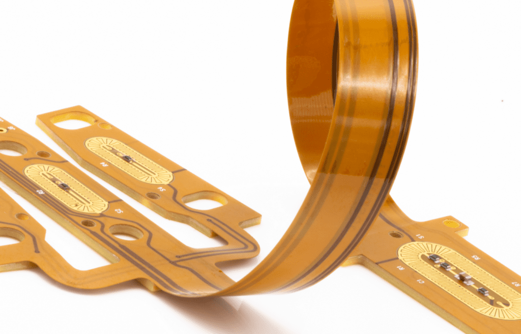
Flexible printed circuit boards have broad and widely accepted applications in different electronic gadgets. These are integral components for improving the functioning of these devices. These are portable, easy to carry, and durable. Our company offers a trustworthy flex printed circuit board variety that boasts up to 8 layers in the manufacturing.
The interconnections are based on the through-hole approach and also include blind micro vias. We are supportive of two different types of inks carbon and silver inks. We have the ability to produce flex PCBs that can be regulated with the help of the technique of hatch impedance.

1. Single-sided flex boards
These have only one conductor layer, which is produced by metals like copper and works with the help of silver ink which is applied on a polyimide or polyester base material during production. The termination features of circuit parts can be accessed either from the top or the bottom. Component leads can make their way through holes present in the base of the PCBs. The process of soldering is done on the annual rings in order to achieve this. These circuits can perform equally well without protective coverings.
2. Double-sided Flex PCB Circuits or dual access flex circuits
These also go by the name of back-bared flex circuits. These also have one conductor layer. But these circuits permit access from both sides in order to choose different features. There are several advantages to using these circuits. But there are some restrictions as well. These circuits are soldered on the base of the board. In this case, the conductors come in contact with the pads of the board. The solder paste is applied to the conductors to make them attach to their positions.
3. Sculptured Flex board Circuits
These are another category of Flex PCBs. There is a distinguished type of circuit multi-step etching technique that these circuits follow for working. This results in a good circuit with copper conductors. However, the length and width of the conductor are different as per the needs of the PCBs. The conductors are small or thin in shape when they are attached in the flexible area; otherwise, these are broad at the point of interconnection.
Procedure To Create Sculptured Flex PCB Prototype
A sculptured flex PCB is the enhanced version of a standard version of flex PCB. The copper traces penetrate the edges of the circuit and work as alternatives to the connector’s male pins. These copper traces have different widths and sizes too. These are really strong to serve as an integral part of a connector. The other portion of the entire circuit is supportive of flexible functions.
This circuit is getting famous since it excludes the connectors and does not need much room as well. The former version of flex PCBs includes combining a connector with a board that already has plated holes. So that the pins can get through these holes or the solder pads that are befitting for the SMT ZIF socket, which is called a zero insertion force socket, this is important to reduce the tension or friction between the connector and the circuit board to which it is getting soldered.
The process of producing a sculptured PCB starts with a broad clad made of copper. Its weight is 3 ounces. This develops the copper traces that move through the edges of the board that forms the pins. The unneeded copper is eliminated. In this way, the width is also reduced, which improves flexibility. The plating process includes the metals like gold, tin, and, most importantly, copper.
These metals are good for developing desired thickness where requisite. The base needs to be excluded as well, which is a dielectric with the help of the back-bearing method. Flex circuits do not use lasers to remove this layer. In this case, drill or pre-punch are two crucial methods that are effective. These unleash the copper traces, which are actually the pins in this case.
Amazing Benefits of Flex PCB Prototype Circuits
The following are some major benefits of this category of flex circuits:
- It excludes the need for ZIF connectors during assembling or production.
- It is beneficial to reduce the cost of the entire circuit assembly.
- The circuit is reliable in terms of Increasing flexibility while working.
- Dual Circuits is an Another type of flex circuit which are quite typical. People nowadays need something that has more circuit parts and more circuit density as well. They also need it to have a power-regulating feature. These features are of a remarkable conductor. The best way is to attach one conductor layer to the base of the circuit. There are many methods to build these circuit boards. These include isolating the conductors from different sides or using overlays for this separation.
Major Drawback
One major drawback of using these circuits is that they are contradictory to the connectivity routes for the circuit parts present on the lower and upper PCB surfaces. There are different solutions available that make driving connectivity through these layers possible. For instance, the metal staples, rivets, and pins were all conductive. The most viable method for improving the interconnectivity channels is called plated through holes. This goes suitable for rigid circuits as well.
- Different layer Flex PCB Prototype Circuits: These circuits comprise more than three layers in total. These are not only expensive but also time-consuming to produce since they are complex kind of circuits. However, these have no parallel in terms of circuit density. The layers are combined with each other strongly and are connected with the help of the pin-through-hole method. These layers are also flexible in nature.
But these are not laminated at all. Instead, the laminating is based on factors like the flexible and dynamic properties of the PCBs and their parts. These circuits are beneficial for applications in the domains of defense and aerospace. These are important to consider in terms of outstanding circuit density. There is room for only 20-25 layers for these circuits because of the substrate and the material of the conductor used in their production. The adhesives can not be befitting, which can negatively influence thermal expansion.
- Rigid-Flex PCB Prototype Circuits: These have a dual nature which is rigid and flexible. Both layers get simultaneous lamination. The rigid nature is useful for the fixation of the circuit parts, while the flexible nature is to develop strong interconnections. These circuits work according to the PTH approach and interconnections made from micro vias. These circuits are integral for applications in the defense domain, where more strength and agility are needed for proper functioning. These circuits are generally found in laptops, drones, and other electronics.
Flex PCB Prototype: Noteworthy Pros and Cons
The variants of flex circuit boards are delicate to appear since the circuit parts are layered on the upper surface and produce less pressure. Due to this reason, it is getting more important to recruit professionals who can design prototypes especially.
So that these will contribute to making this industry flourish. There are many significant reasons why different sectors are incorporating flex circuits in their electronics.
The main objective of these circuits is to highlight the importance of useful connectors. These are for reducing the product price as well. Such circuitry also helps in eliminating the odds of dysfunctional solder joints for smooth working.
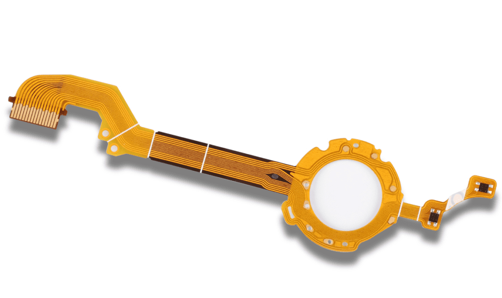
These circuits are also crucial for adjusting to restricted areas, like in a smartwatch. These can easily cope with the mechanical vibration, movements of their counterparts, the friction produced by them, and much more technicalities.
In this case, flex circuits are beneficial. There are some obvious drawbacks to these circuits as well. The development of a flex printed circuit board is not easy and simple as a rigid circuit board.
The overall price ranges are different in both cases, along with the repair cost and the material used for manufacturing as well.
These are some major factors that differentiate between the rigid and flex types of printed circuit boards for the designers, manufacturers, and users.
It reduces the chances of any mishaps and misunderstandings for everyone associated with these circuits and their utilization.
