Metal printed circuit boards are a subset of the PCB family with a metal basis in the heat-spreader region. A thermal insulating layer, also called an IMS layer, a copper foil, and a metal plate are the three components that make up a multi-layer printed circuit board. It has high mechanical strength, superb processing properties, heat dissipation, good magnetic conductivity, and a high tensile modulus.
Methods involving the use of both conductive and non-conductive materials are used to achieve this result. Most metal printed circuit boards (PCBs) include aluminum or copper as their base material or a combination of aluminum and copper or another metal alloy.
Copper-core printed circuit boards are more expensive but more dependable than aluminum-core PCBs. It’s not hard to imagine if you factor in the higher cost of copper. Since aluminum PCBs are far more cost-effective than copper core PCBs, clients often want these. Metal PCBs are often used for thermoelectric separation.
Due to the metal PCB’s efficiency in transforming electrical current into optical radiation (light), LEDs are used to fill the void left by older technologies.
Even LEDs waste some of the current they’re fed by producing heat, as do all other electrical gadgets. Reducing heat loss is essential for increasing LED durability, reliability, performance, and energy efficiency. Metal PCBs are more efficient in dissipating the heat produced by LEDs.
In modern LED applications, PCBs consisting of FR4 material with thermal through arrays, thick copper, aluminum, and copper metal cores, and other advanced features are used. In addition to copper-clad-steel (or FR4) printed circuit boards with thermal through the array, aluminum metal-core PCBs are also widely used.
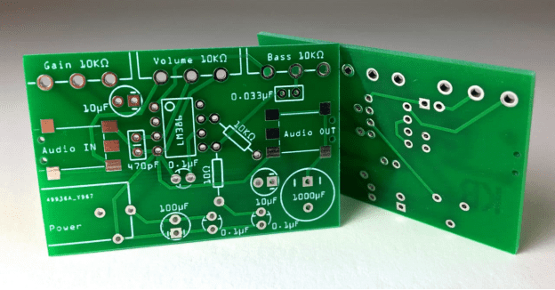
Metal PCB Materials and Thickness
Thermal PCB metal might be aluminum, copper, or exotic alloys. Aluminum core PCBs are widespread. Brass or steel are considered but not recommended. Hard metals make PCB cutting difficult.
Other concerns in selecting metal PCB materials are manufacturing chemicals and metal reactions. Thicker and thinner metal in PCB base plates is feasible.
Importance of Heat Dissipation and Thermal Resistance

The most widely used material for printed circuit boards is FR4, a flame-retardant epoxy laminate. This building approach, however, results in FR4’s poor heat conductivity.
Average measurements show that a 1.6 mm thick, 270 mm2 FR4 board has a thermal resistance of around 30 °C/W when heated in a plane.
One-dimensional thermal resistance rises to over 700 °C/W when considering a heat source with dimensions closer to that of an LED (3.3 x 3.3 mm), making it practically impossible to keep the LED junction temperature within working limits.
When designing FR4-printed circuit boards, heat vias are one low-cost way used to boost thermal resistance. Plated holes connect two conducting layers (PTH).
By strategically placing PTH vias, designers may increase an FR4 board’s thermal stability. In the case when the thermal through is filled with solder and the heat source is perpendicular to it, the thermal resistance is 96.8 °C/W.
Increasing the number of thermal vias may significantly enhance thermal resistance. Our prior 270 mm2 board’s thermal resistance was 20 °C/W, but we were able to cut it in half by filling five 0.6 mm vias with solder.
Note that open vias have higher thermal resistance than filled vias due to the reduced area perpendicular to the heat source. The structure of the metal printed circuit board varies greatly depending on the manufacturer.
A single-layer multi-core printed circuit board has a solder mask, a copper circuit layer on top, a thermally conductive dielectric layer, and an aluminum substrate as the metal base layer.
The three layers are laminated and glued together during fabrication to form a heat conductor. Most designers choose aluminum. However, steel and copper substrates are sometimes used.
Using the same parameters, we find that the thermal resistance of a 1.6-mm-thick, 270-mm-square metal PCB is 0.2 °C/W. The PCB’s thermal resistance increases to 5.3 °C/W if the heat source is, once again, 3.3 mm.
To be sure, this is a substantial improvement over the thermal resistance of a standard FR4 PCB equipped with thermal vias. The PCB dielectric is the primary limiting factor for metal PCB core materials.
Advantages of Metal PCB Design over Standard Circuit Boards
The thermal expansion and dimensional stability of metal PCB material are much enhanced over those of standard circuit board material. A metal core PCB layout may improve power density, electromagnetic shielding, and capacitive coupling.
Even though they are not strictly necessary, thermal vias are often added to metal PCB prototypes in an effort to enhance their thermal performance. When small housing of high-power LED lighting is needed, engineers generally pick copper metal PCB LEDs due to copper’s better thermal qualities compared to those of aluminum.
To prepare a printed circuit board for an LED chip, the builder must first carefully remove the dielectric layer, exposing the metal. Increased efficiency results from the direct thermal channel’s decreased thermal resistance.
The center of metal is used for thermoelectric separation by producers of printed circuit boards. The heat is dissipated more efficiently because the microchip or die is in direct contact with the metal core.
They use wire bonding to create electrical connections between the traces on the circuit board. For the metal PCB, this means they can attain a higher thermal conductivity of above 200 W/mk.
With the use of metal-core printed circuit boards (PCBs), it is possible to avoid the need for additional space-hogging components such as heat sinks, which reduces the board’s overall size.
When a metal substrate is present, installing extra components like power transistors is significantly simpler because mica, grease, and rubber insulators are not present underneath the power devices, eliminating the insulating components to achieve better heat transmission.
By using etched traces on the metal PCBs, designers can eliminate entire rows of interconnects on printed wiring boards. Surface-mount power and passive devices can also be used to replace several discrete components on the board.
Advantages of Metal PCBs
Insulated metal substrate technology excels when large amounts of heat must be removed. Since metal printed circuit boards (PCBs) have many benefits over FR4 PCBs, they are widely used by engineers and designers.
- They are capable of integrating a dielectric polymer layer that has high thermal conductivity for the purpose of lowering thermal resistance.
- They have the ability to transmit heat up to eight to nine times more quickly than FR4 PCBs.
- They can dissipate heat, reducing the temperature of heat-generating components and thereby increasing both their performance and their lifespan.
Making a Metal Printed Circuit Board
Utilize the panel’s dimensions as a template for cutting a single-sided Metal PCB laminate to the required size. Make sure the holes are somewhat larger than the PTHs you’ll be using (often by 1 mm).
After the holes have been made, the electrical connection between the outer layers and the metal is sealed using resin. Laminate It is usual practice to rough up the back of the metal using abrasive paper before adhering copper foil to polypropylene (PP).
The copper foil sheet, polypropylene (PP) dielectric layer, and CCL made in step one must be pressed and bonded together to form a double-sided Metal PCB laminate. Next, holes are drilled in the same locations as the previous time, but this time they are made in the cured resin, where they would ultimately form PTHs.
From then on out, creating a single-sided PCB is identical to creating a double-sided one. Multilayer copper and aluminum core printed circuit boards that are double-sided are more challenging to manufacture than similar single-sided boards.
Manufacturing of Double-sided Metal PCBs
Below are the following steps involved in manufacturing a double-sided Metal PCB:
- Cut the metal PCB laminate to size.
- 1st Drilling: Drill 1mm bigger holes at PTH positions.
- Fill drilled holes with epoxy to insulate the outer layers from the metal.
- Laminate Abrading the metal’s backside to attach the copper foil to PP.
- Laminate and press the PP (dielectric layer), single-sided CCL, and copper foil (one sheet) to make a double-sided Metal PCB laminate.
- 2nd Drilling: Drill holes on the cured resin in the same positions as the 1st drilling.
- After then, production is the same as double-sided PCBs. Double-sided Metal PCB, copper core, and aluminum core PCB fabrication are more complicated. MADPCB is a trustworthy Metal PCB manufacturer that supports Metal PCB prototypes and manufacturing.
How Does PCB Thermal Management Work Using a Metal With a Pedestal?
Thermal management is often performed by employing a metal constructed out of copper or aluminum, with the circuit layer and the dielectric layers placed on top of it.
Transferring heat from warm components to a cooler environment is essential. Without adequate temperature management, the performance of any application might suffer. A copper pedestal is preferable because of copper’s high thermal conductivity compared to that of other materials.
PCBs benefit from the increased heat conductivity provided by a copper pedestal (PCBs). The copper in the pedestal’s metal promotes heat conductivity and keeps internal parts cooler. Copper is an option that may help lower the heat stress on PCBs.
As the quantity of heat produced by printed circuit boards (PCBs) has increased due to shrinking, integrated and stacked components and other causes, thermal management has become an essentially important part of PCB design.
No matter what printed circuit board (PCB) substrate, design layout, or manufacturing process you choose for your project, the experts at San Francisco Circuits can help you identify the best option.
