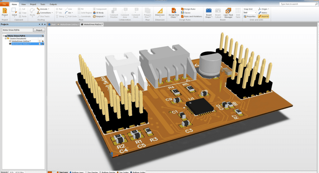
Oshpark is a popular printed circuit board (PCB) manufacturer known for its high-quality PCBs and affordable prices. In recent years, Oshpark has added support for Altium Designer, a popular PCB design software used by engineers and designers around the world.
Altium Designer is a powerful tool for designing complex PCBs with ease. With Oshpark’s support for Altium Designer, designers can now easily order high-quality PCBs directly from the software. This integration streamlines the PCB design process, allowing designers to focus on their designs rather than the logistics of ordering PCBs.
Oshpark’s support for Altium Designer has been well-received by the electronics community. Designers praise the ease of use and affordability of Oshpark’s PCB manufacturing, while Altium Designer users appreciate the convenience of ordering PCBs directly from the software. Overall, the integration of Oshpark and Altium Designer has made the PCB design process more efficient and accessible for designers and engineers alike.

Getting Started with Oshpark Altium
Creating a New Project
To get started with Oshpark Altium, the first step is to create a new project. This can be done by selecting “File” from the menu bar and then choosing “New Project.” Give the project a name and select a location to save it.
Adding Schematic Symbols
After creating a new project, the next step is to add schematic symbols. This can be done by selecting “File” from the menu bar and then choosing “New” and “Schematic.” From there, you can add schematic symbols by selecting the “Place” option from the toolbar and then choosing the desired symbol from the library.
Designing the PCB Layout
Once the schematic symbols have been added, the next step is to design the PCB layout. This can be done by selecting “File” from the menu bar and then choosing “New” and “PCB.” From there, you can add components by selecting the “Place” option from the toolbar and then choosing the desired component from the library. Once all components have been added, you can then connect them by selecting the “Route” option from the toolbar and then choosing the desired connection method.
Generating Gerber Files
After designing the PCB layout, the final step is to generate Gerber files. This can be done by selecting “File” from the menu bar and then choosing “Fabrication Outputs” and “Gerber Files.” From there, you can select the desired output options and then generate the Gerber files.
Overall, Oshpark Altium is a powerful tool for designing PCB layouts. By following these simple steps, you can get started with Oshpark Altium and begin designing your own PCB layouts.
Advanced Techniques for Oshpark Altium

Using Differential Pairs
Differential pairs are a great way to reduce noise and improve signal integrity in your PCB designs. Oshpark Altium makes it easy to create and use differential pairs. To create a differential pair, select the two traces you want to use and right-click to open the Properties panel. Under the Routing tab, select the Differential Pair option and choose the appropriate settings for your design.
Creating Custom Footprints
Custom footprints can be a great way to add unique components to your PCB designs. Oshpark Altium makes it easy to create custom footprints. To create a custom footprint, open the Footprint Editor and select the appropriate package type. From there, you can add pads, vias, and other components to create a custom footprint that meets your specific needs.
Design Rule Check (DRC) Settings
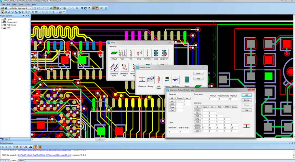
Design Rule Check (DRC) settings are an important part of any PCB design process. Oshpark Altium makes it easy to set up and customize your DRC settings. To access the DRC settings, go to the Design menu and select Rules. From there, you can set up rules for spacing, clearance, and other design parameters.
Importing and Exporting Design Files
Importing and exporting design files is an important part of collaborating on PCB designs. Oshpark Altium makes it easy to import and export design files in a variety of formats. To import a design file, go to the File menu and select Import. From there, you can select the appropriate file format and import your design. To export a design file, go to the File menu and select Export. From there, you can select the appropriate file format and export your design.
Overall, Oshpark Altium provides a powerful set of tools for creating and working with PCB designs. By using advanced techniques like differential pairs, custom footprints, DRC settings, and importing/exporting design files, you can take your designs to the next level.
Troubleshooting Oshpark Altium

Common Errors and Solutions
When working with Oshpark Altium, there are several common errors that can occur. One of the most common errors is the “No matching rule found” error. This error occurs when the design rules in Altium do not match the manufacturing capabilities of Oshpark. To solve this error, you need to update the design rules to match the manufacturing capabilities of Oshpark.
Another common error is the “Component not found” error. This error occurs when the components used in the design are not available in the Oshpark library. To solve this error, you need to either find an alternative component in the Oshpark library or create a custom component.
Debugging the Design Process
Debugging the design process in Oshpark Altium can be a challenging task. One of the most effective ways to debug the design process is to use the Design Rule Check (DRC) feature in Altium. The DRC feature checks the design against a set of rules to identify any errors or inconsistencies.
Another way to debug the design process is to use the netlist feature in Altium. The netlist feature creates a list of all the components and their connections in the design. This can help identify any errors or inconsistencies in the design.
In conclusion, troubleshooting Oshpark Altium requires a clear understanding of the common errors and solutions, as well as effective debugging techniques. By following these tips, you can ensure a successful design process with Oshpark Altium.
Related posts:
- The Complete Guide to Micro Electronic Assembly and How It is Disrupting the Manufacturing Industry
- Why Blue PCB is Gaining Popularity in the PCB Industry
- What Is The Average Circuit Board Cost, And What Factors Determine The Pricing?
- LTM8033IY#PBF is an EMC-Compatible µModule Buck Converter: Here’s How It Works

