Prototype board layout is an essential aspect of circuit design. It refers to the physical arrangement of electronic components on a board which facilitates the creation of a functional circuit. The layout of a prototype board plays a crucial role in determining the performance, reliability, and manufacturability of a circuit.
The design of a prototype board should be carefully planned and executed to ensure that the circuit functions as intended. A well-designed layout can reduce the likelihood of errors, improve signal integrity, and make it easier to troubleshoot and modify the circuit. Factors such as component placement, routing, and thermal management must be considered during the layout process to optimize the performance of the circuit. By paying close attention to these details, designers can create a prototype board that meets the desired specifications and can be easily replicated for mass production.
Basics
What is a Prototype Board Layout?
A prototype board layout is a physical representation of a circuit design that allows for easy testing and modification of the circuit. It is used in the early stages of product development to ensure that the circuit functions as intended before moving on to more expensive and permanent manufacturing methods.
Prototype board layouts can be created using a variety of methods, including breadboards, stripboards, and printed circuit boards (PCBs). Each method has its own advantages and disadvantages, and the choice of method depends on factors such as complexity, cost, and time constraints.
Types of Prototype Board Layouts
There are three main types of prototype board layouts: breadboards, stripboards, and PCBs.
Breadboards
Breadboards are the simplest and most common type of prototype board layout. They consist of a plastic board with a grid of holes that are connected by metal strips. Components can be inserted into the holes and connected by jumper wires to create a circuit.
Breadboards are easy to use and allow for quick testing and modification of circuits. However, they are not suitable for complex circuits or high-frequency applications due to their limited space and poor signal integrity.
Stripboards
Stripboards, also known as veroboards, are similar to breadboards but have pre-made copper strips that run along the board. Components can be soldered onto the strips to create a circuit.
Stripboards are more suitable for complex circuits than breadboards, as they allow for more precise and permanent connections. However, they can be time-consuming to create and modify.
PCBs
PCBs are the most professional and permanent type of prototype board layout. They consist of a thin board made of insulating material with a layer of copper on one or both sides. The copper is etched away to create a circuit pattern, and components are soldered onto the board.
PCBs are suitable for complex circuits and high-frequency applications, as they offer precise and reliable connections. However, they are more expensive and time-consuming to create than breadboards or stripboards.
In summary, prototype board layouts are an essential tool in the early stages of product development. Choosing the right type of layout depends on factors such as complexity, cost, and time constraints. Breadboards are suitable for simple circuits, stripboards for more complex circuits, and PCBs for professional and permanent designs.
Design Considerations

When designing a prototype board layout, there are several important factors to consider. These include schematic design, component placement, trace routing, and power and ground planes.
Schematic Design
The schematic design is the foundation of the prototype board layout. It is important to ensure that the schematic is accurate and complete before moving on to the layout stage. A well-designed schematic will make the layout process easier and more efficient.
Component Placement
The placement of components on the board is critical to the success of the design. Components should be placed in a logical and organized manner to minimize the length of the traces and reduce the risk of signal interference. It is also important to consider the physical size of the components and ensure that they fit within the available space on the board.
Trace Routing
Trace routing refers to the process of connecting the components on the board with traces. It is important to keep the traces as short as possible to minimize the risk of signal interference and ensure that the circuit operates correctly. The use of ground planes can also help to reduce signal interference and improve the overall performance of the circuit.
Power and Ground Planes
The power and ground planes are critical components of any prototype board layout. They provide a stable reference voltage for the circuit and help to reduce the risk of signal interference. It is important to ensure that the power and ground planes are designed correctly and that they are connected to the appropriate components on the board.
In summary, when designing a prototype board layout, it is important to consider the schematic design, component placement, trace routing, and power and ground planes. By paying attention to these key factors, you can create a prototype board that is efficient, reliable, and easy to use.
Tools and Software
Hardware Tools
The following hardware tools are essential for creating a prototype board layout:
- Soldering iron: used to solder components onto the board
- Multimeter: used to measure voltage, current, and resistance
- Wire strippers: used to strip insulation from wires
- Pliers: used to bend and cut wires and components
- Breadboard: used to prototype circuits without soldering
Software Tools
The following software tools are essential for creating a prototype board layout:
- Eagle: a popular PCB design software that allows you to create schematics and layout boards
- KiCAD: an open-source alternative to Eagle that offers similar functionality
- LTSpice: a simulation software that allows you to test your circuit before creating a physical board
- GitHub: a version control system that allows you to collaborate with others and keep track of changes to your design files
When selecting software tools, it’s important to consider your budget, the complexity of your design, and the learning curve of the software. It’s also important to keep in mind that some software tools may have limitations or require additional plugins or libraries to fully meet your needs.
Manufacturing
When it comes to manufacturing prototype boards, there are three main stages: PCB fabrication, assembly, and testing. Each stage plays a crucial role in ensuring the final product meets the desired specifications.
PCB Fabrication
The first stage of manufacturing is PCB fabrication. This involves creating the physical board that will house the components. There are several methods for PCB fabrication, including:
- Etching: This involves using a chemical process to remove unwanted copper from the board, leaving behind the desired circuit pattern.
- Milling: This involves using a CNC machine to remove unwanted copper from the board.
- Additive: This involves using a 3D printer to create the board layer by layer.
Once the board has been fabricated, it is important to inspect it for any defects or errors before moving on to the next stage.
Assembly
The second stage of manufacturing is assembly. This involves placing the components onto the board and soldering them in place. There are two main methods for assembly:
- Manual assembly: This involves placing the components onto the board by hand and soldering them in place using a soldering iron.
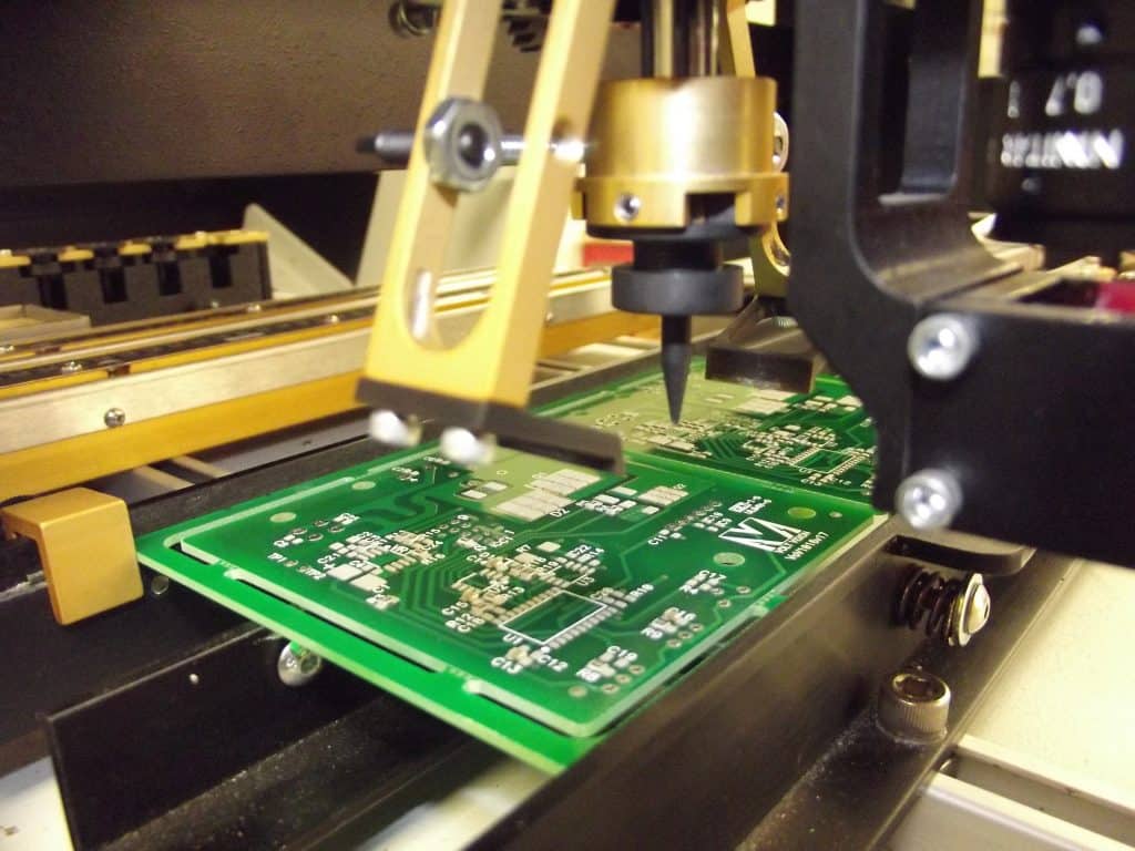
- Automated assembly: This involves using a pick-and-place machine to place the components onto the board and a reflow oven to solder them in place.
Regardless of the method used, it is important to ensure that the components are placed correctly and soldered securely.
Testing
The final stage of manufacturing is testing. This involves checking the board to ensure that it functions as intended. There are several methods for testing, including:
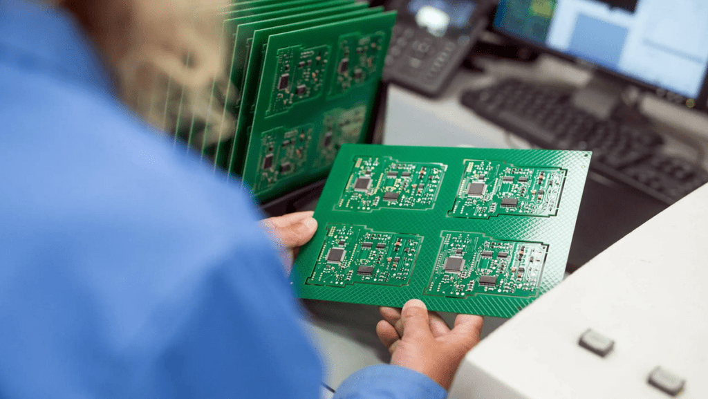
- Visual inspection: This involves checking the board for any visible defects or errors.
- Electrical testing: This involves using a multimeter or other testing equipment to check the board’s electrical properties.
- Functional testing: This involves testing the board in a real-world scenario to ensure that it performs as intended.
By thoroughly testing the board, any issues can be identified and addressed before the final product is released.
In conclusion, the manufacturing process for prototype boards involves several stages, each of which plays a crucial role in ensuring the final product meets the desired specifications. By carefully fabricating the board, assembling the components, and testing the final product, a high-quality prototype board can be produced.
Conclusion
In summary, prototype board layout plays a crucial role in the development of electronic systems. It is the foundation upon which the entire system is built, and any mistakes made during the layout process can result in significant delays and added costs.
When designing a prototype board layout, it is important to consider factors such as component placement, signal routing, and power distribution. By carefully planning and executing the layout, designers can ensure that the system operates optimally and meets all necessary specifications.
Throughout this article, we have discussed various best practices and techniques for creating an effective prototype board layout. These include using a grid system for component placement, minimizing the length of signal traces, and ensuring proper grounding and decoupling.
By following these guidelines, designers can create prototype board layouts that are reliable, efficient, and cost-effective. While there is always room for improvement and optimization, the techniques discussed in this article provide a solid foundation for any prototype board layout project.
