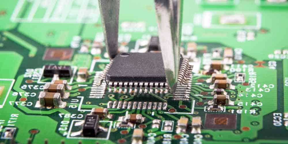
Surface mount technology (SMT) has revolutionized the electronics industry by allowing for the miniaturization of electronic components. SMT involves the mounting of components directly onto the surface of a printed circuit board (PCB), as opposed to the traditional through-hole method. This allows for a more compact and efficient design, as well as easier and faster assembly.
SMT components are typically smaller and lighter than their through-hole counterparts, making them ideal for portable and handheld devices. They also have a lower profile, which can reduce the overall size of the PCB. Additionally, SMT components can be placed closer together, allowing for more components to fit onto a single board. This can lead to a reduction in the number of PCBs required for a particular design, ultimately lowering production costs.
What is SMT in PCB
Definition of SMT
Surface Mount Technology (SMT) is a method of assembling electronic circuits where the components are mounted directly onto the surface of a printed circuit board (PCB). This method replaces the traditional through-hole technology where components are inserted into holes drilled in the PCB.
SMT components are usually smaller and lighter than through-hole components, and they are placed on the PCB using automated machines. The components are held in place by solder paste, which is applied to the PCB before the components are placed. The solder paste is then melted using a reflow oven, which fuses the components to the PCB.
Advantages of SMT
SMT has several advantages over through-hole technology. First, SMT components are much smaller, which allows for smaller and more compact PCB designs. This is especially important in modern electronics where space is at a premium.
Second, SMT components are faster and easier to assemble than through-hole components. This is because SMT components can be placed on the PCB using automated machines, which reduces the need for manual labor.
Third, SMT components are more reliable than through-hole components. This is because SMT components have fewer mechanical connections than through-hole components, which reduces the risk of failure due to vibration or shock.
Finally, SMT components are cheaper than through-hole components. This is because SMT components are easier and faster to assemble, which reduces the cost of labor. Additionally, SMT components are smaller and lighter, which reduces the cost of shipping and storage.
In conclusion, SMT is a method of assembling electronic circuits that offers several advantages over traditional through-hole technology. SMT components are smaller, faster, more reliable, and cheaper than through-hole components, which makes them ideal for modern electronics.
SMT Components

Types of SMT Components
Surface Mount Technology (SMT) is a method of assembling electronic circuits where the components are mounted directly onto the surface of the printed circuit board (PCB). SMT components come in various types, including:
- Resistors: SMT resistors are small and can be rectangular or cylindrical. They are used to limit current and voltage in electronic circuits.
- Capacitors: SMT capacitors come in different shapes and sizes, including rectangular, cylindrical, and disc. They are used to store electrical charge and filter signals.
- Diodes: SMT diodes are small and can be rectangular or cylindrical. They are used to control the direction of current flow in electronic circuits.
- Transistors: SMT transistors are small and can be rectangular or cylindrical. They are used to amplify or switch electronic signals.
- Integrated Circuits (ICs): SMT ICs are small chips that contain multiple transistors, resistors, capacitors, and other components. They are used to perform complex functions in electronic circuits.
Examples of SMT Components
SMT components can be found in a wide range of electronic devices, including smartphones, laptops, and televisions. Here are a few examples of SMT components:
- Surface Mount Resistors: These resistors are used in a variety of electronic circuits, including power supplies, audio amplifiers, and LED drivers.
- Surface Mount Capacitors: These capacitors are used in power supplies, audio amplifiers, and filters.
- Surface Mount Diodes: These diodes are used in power supplies, LED drivers, and signal processing circuits.
- Surface Mount Transistors: These transistors are used in audio amplifiers, power supplies, and switching circuits.
- Surface Mount ICs: These ICs are used in a variety of electronic devices, including smartphones, laptops, and televisions.
In conclusion, SMT components play a crucial role in modern electronic devices. They are small, lightweight, and reliable, making them ideal for use in compact and portable devices.
SMT Assembly Process
Solder Paste Application
The first step in surface mount technology (SMT) assembly is the application of solder paste to the printed circuit board (PCB). Solder paste is a mixture of tiny metal balls of solder and flux, which is a chemical that helps the solder stick to the PCB. The paste is applied to the PCB using a stencil, which is a thin metal sheet with holes cut out where the solder paste needs to be applied. The stencil is placed over the PCB and the solder paste is spread over the holes using a squeegee. Once the solder paste is applied, the stencil is removed and the PCB is ready for the next step.
Component Placement
The next step in the SMT assembly process is component placement. This is where the electronic components are placed onto the PCB in their correct positions. This is done using a pick-and-place machine, which is a robotic arm that picks up the components from a tray or reel and places them onto the PCB. The machine uses a camera to ensure that the components are placed in the correct position and orientation. Once all the components are placed, the PCB is ready for the next step.
Reflow Soldering
The final step in the SMT assembly process is reflow soldering. This is where the solder paste is melted to form a permanent connection between the components and the PCB. The PCB is placed into a reflow oven, which heats the PCB to a temperature high enough to melt the solder paste. The oven is carefully controlled to ensure that the temperature is even across the PCB and that the solder paste melts at the correct rate. Once the solder paste has melted, the PCB is cooled down and the SMT assembly process is complete.
In conclusion, the SMT assembly process is a complex but essential part of modern electronics manufacturing. By following the steps of solder paste application, component placement, and reflow soldering, manufacturers can create high-quality, reliable electronic products.
SMT vs Through-Hole Technology
Comparison of SMT and Through-Hole Technology
Surface-mount technology (SMT) and through-hole technology are two methods of mounting electronic components onto a printed circuit board (PCB). Through-hole technology involves drilling holes in the PCB and inserting components through the holes, then soldering them in place. SMT involves directly mounting components onto the surface of the PCB, and then soldering them in place.
Advantages and Disadvantages of SMT vs Through-Hole Technology
Advantages of SMT
- Smaller size: SMT components are much smaller than through-hole components, allowing for smaller and more compact PCB designs.
- Higher component density: Because SMT components can be placed closer together, PCBs can have a higher component density.
- Faster production: SMT components can be placed and soldered by machines, leading to faster and more automated production.
- Lower cost: SMT components are often less expensive than through-hole components due to their smaller size and automated production.
Disadvantages of SMT
- More difficult to repair: SMT components are harder to remove and replace, making repairs more difficult.
- Sensitive to heat: SMT components can be damaged by excessive heat during soldering, requiring careful temperature control.
- Limited power handling: SMT components are generally not as robust as through-hole components and may have lower power handling capabilities.
Advantages of Through-Hole Technology
- Stronger mechanical connection: Through-hole components are mechanically secured to the PCB through the holes, providing a stronger connection.
- Easier to repair: Through-hole components can be easily removed and replaced, making repairs easier.
- Higher power handling: Through-hole components are generally more robust and can handle higher power than SMT components.
Disadvantages of Through-Hole Technology
- Larger size: Through-hole components are larger than SMT components, limiting the density of components on a PCB.
- Slower production: Through-hole components require manual insertion and soldering, leading to slower and less automated production.
- Higher cost: Through-hole components are often more expensive than SMT components due to their larger size and manual production.
In conclusion, both SMT and through-hole technology have their advantages and disadvantages, and the choice between the two depends on the specific requirements of the PCB design and production process.
Design Considerations for SMT
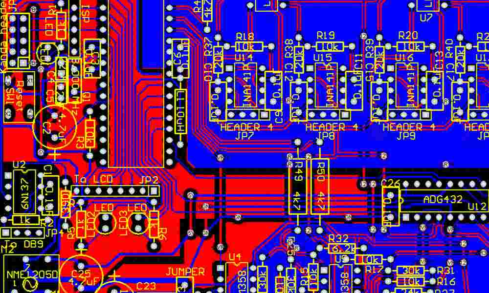
PCB Layout Guidelines for SMT
When designing a PCB for surface mount technology (SMT), it is important to consider the layout of the components and their respective footprints. One of the main advantages of SMT is the ability to place components closer together, which can result in smaller and more compact designs. However, this also means that the spacing and orientation of the components must be carefully planned to avoid any interference or short circuits.
To ensure proper SMT placement, it is recommended to follow the following PCB layout guidelines:
- Use a grid system to ensure consistent spacing between components
- Place components in a logical and organized manner
- Avoid overlapping components
- Keep sensitive components, such as RF circuits, away from noisy components, such as power supplies
- Use ground planes and power planes to reduce noise and improve signal integrity
- Ensure that the PCB has adequate clearance and spacing for the assembly process
Component Selection for SMT
When selecting components for SMT, it is important to consider their size, shape, and orientation. Unlike through-hole components, SMT components are typically smaller and have a specific orientation, which must be taken into account during the design process. Additionally, some components may require special handling or placement to ensure proper function and reliability.
To ensure proper component selection for SMT, it is recommended to follow the following guidelines:
- Choose components with appropriate footprints and package sizes for SMT assembly
- Consider the orientation and polarity of components, such as diodes and capacitors
- Use components with a high tolerance for temperature and vibration
- Avoid using components with large thermal mass, as they may affect the soldering process
- Consider the availability and reliability of the components
By following these guidelines, designers can ensure that their SMT designs are optimized for performance, reliability, and manufacturability.
SMT Inspection and Quality Control

Inspection Techniques for SMT
SMT (Surface Mount Technology) inspection is critical to ensure the quality and reliability of the PCB (Printed Circuit Board) assembly. There are various techniques used for SMT inspection, including visual inspection, automated optical inspection (AOI), and X-ray inspection.
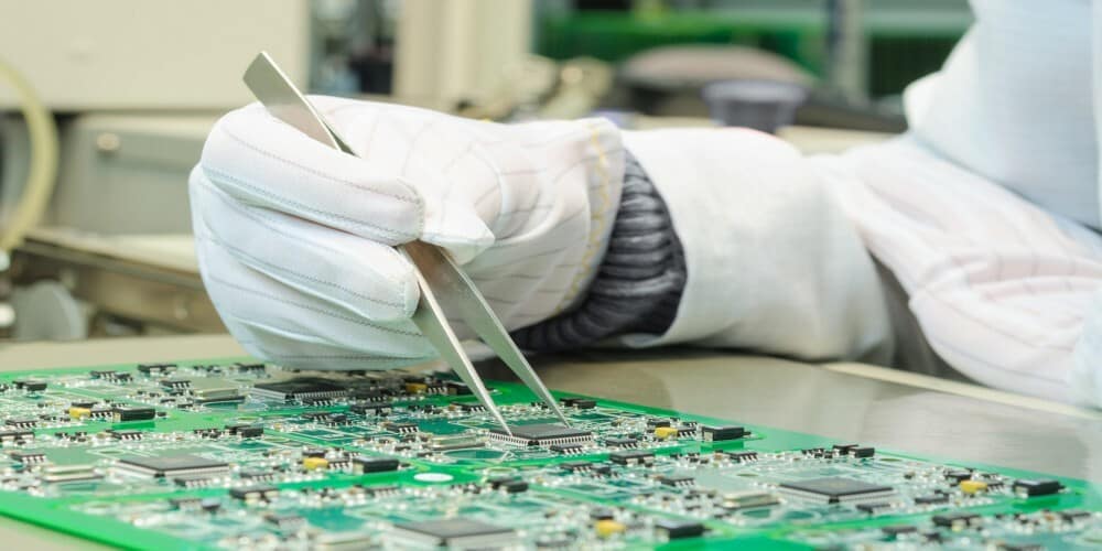
Visual inspection is a manual inspection process that involves examining the SMT components and PCB for any defects or abnormalities. This inspection method is suitable for detecting visible defects such as missing components, incorrect component placement, and solder bridging.
AOI is an automated inspection technique that uses cameras and software to detect defects in SMT components and PCBs. This inspection method is faster and more accurate than visual inspection and can detect defects such as incorrect component orientation, lifted leads, and solder joint defects.
X-ray inspection is a non-destructive inspection technique that uses X-rays to inspect the internal structure of SMT components and PCBs. This inspection method is suitable for detecting hidden defects such as voids in solder joints, component misalignment, and PCB layer alignment issues.
Quality Control Measures for SMT Assembly
Quality control measures are essential to ensure that the SMT assembly meets the required quality standards. Quality control measures for SMT assembly include process control, component traceability, and testing.
Process control involves monitoring and controlling the SMT assembly process to ensure that it is performed correctly and consistently. This includes monitoring the temperature and humidity levels, ensuring that the correct components are used, and verifying that the correct soldering parameters are used.
Component traceability is the process of tracking the components used in the SMT assembly. This includes identifying the supplier, part number, date code, and batch number of each component. Component traceability is essential for identifying and addressing any quality issues that may arise.
Testing is the final step in the SMT assembly process and is used to verify that the PCB functions correctly. Testing can be performed using various techniques, including functional testing, in-circuit testing, and boundary scan testing.
In summary, SMT inspection and quality control are critical to ensure the quality and reliability of the PCB assembly. Various inspection techniques and quality control measures are used to detect defects and ensure that the SMT assembly meets the required quality standards.
