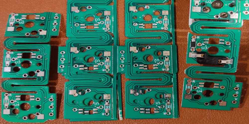
In the world of contemporary consumer electronics, PCB design and production have come to play a crucial role. Nevertheless, hiring local businesses to design and create your PCB might be quite expensive and dirty.
When ordering and or designing PCBs utilizing local services, a variety of extra issues arise, including a lack of pre/post sales assistance, inconsistencies in the design specifications, human errors that result in overbudgeting, etc. Hence, using the top EasyEDA PCB CAD program, I will walk everyone through a comprehensive PCB design lesson in this post.

What is EasyEDA PCB Design Software?
The name EasyEDA alone suggests that designing circuits is simple. Embedded, electrical, and hardware engineers, among many others, can build a circuit using this web-based tool, simulate it, share it, and examine the schematics, PCBs, and simulations of the circuit. Coupled with the LCSC components, this tool assists users in putting their thoughts into action.
Electronics engineers, students, educators, enthusiasts, and makers can create and share their designs with the help of the more user-friendly and effective online tool for PCB design known as EasyEDA. EDA means electronics design automation, while EasyEDA can be described as a tool that can assist you in rapidly and easily designing your desired PCB.
Regardless of whether you have a certain layout in mind, the software is ideal for you. You can experiment with various layouts, without the need to pay one cent. You can get the application downloaded or use the free online version to execute the program.
The ideal PCB design program for novices is EasyEDA. You will discover this tool to be a practical answer for any design, no matter what outcome you wish to produce with the board.
Features of the EasyEDA PCB Design Software
EasyEDA PCB design program is incredibly dependable, stable, and simple to use. Its user interface runs smoothly and with great responsiveness. Thousands of schematic examples can be found in EasyEDA’s extensive library, along with thousands electronic components meant for use in circuits, circuit boards, as well as modeling. The library is open to use and expansion by anyone. Also, I t can alter designs that have already been created in Altium, KiCad, and Eagle, after importing them, then make your edits in EasyEDA.
Users of EasyEDA can access the Open Source module created by many electronics engineers, which is yet another remarkable feature of the program.
Assimilated with many features, the tool remains as the finest and also most used circuit construction tool for so many. Simple elements/features of EasyEDA include:
- Displays more straightforward and effective circuit design capabilities
- Shares content both privately and publicly
- Can create a variety of open-source projects
- Endorses scripting and offers API
- Integrated with features for PCB fabrication and component purchasing
- Online project sharing
- Theme setting
- Document recovery at all levels
- Exporting documents through PDF, PNG, and SVG forms
- Extract of Netlist from programs like FreePCB, Pads, Spice, as well as Altium Designer
- Checking the design rules
- DXF/BOM exports
- Access to numerous public libraries
- PCB module
- Management of different libraries
- Creation as well as editing of footprint
- Creation as well as editing of the symbol or subpart as well as the spice model/symbol
How to Design a Schematic Diagram with EasyEDA PCB Design Software

Determine how to operate the software
You can select between offline as well as online modes using EasyEDA. You may launch its Online Editor within a matter of seconds if you’d like to start using the program right away. Instead, download for free the Windows, Mac, and Linux versions of its Desktop Client.
The software’s essential functions are always free. But, if you decide to subscribe, you’ll receive a lot of beneficial extra benefits.
Begin a project
When you launch EasyEDA, you are ready to start working on the schematic. To begin, start the new project.
Putting Components in Place
On your design, you may find a variety of elements to include in the schema. The symbol is added to the project by clicking it from the menu but then dragging it there.
You’re welcome to peruse the library’s many items, which are arranged in a number of categories. Users can also perform a search for just a specific element. What you must do is type the search term into the search box.
Join Components
Components and resistors are connected next. To do so, simply press the keyboard’s “W” key. This will launch a wiring tool that will assist you in connecting everything.
Finish the procedure.
The necessary components should now be placed inside your PCB’s edge. Choose them, then connect them with PCB tools.
How to Design a Board with EasyEDA
The board outline needs to be made before the footprints are placed. Inside this board outline surface, draw your outline and so this functions as its active layer. Draw its outline using PCB tools palette’s Arc or Track options. The utility tries to build a board by itself when it converts the schematic into a PCB. Generally speaking, the outline area of the default board is over 1.5 times larger than the sum of all footprints combined.
Because there is room for tracking in this design, whole footprints could be placed within it. By taking off certain components, you can alter the board anyway you like. By removing the arc and dragging lines from the “Properties” menu, a simple rectangular board can be made.
Options for board outlines include rounded rectangular, circular, and rectangular, which are directly provided by the tool. The DXF file must be loaded in order to design board outlines that are more intricate.
Factors to Consider while Designing Circuits

User interfaces
The effect on PCB design is demonstrated by where components like the power supply, audio cables, potentiometers, and LED displays are placed.
Layers of PCB
Because it can be challenging to trace the paths without running into other components, designing intricate circuits on the single layer can be fairly challenging. It is better to utilize two copper layers with traces on the two sides of this board for this. Traces on either of the board’s sides can be joined using the option called “via”.
A via is an established link between layers that is represented by the copper-plated holes inside the board.
Ground Layers
There is going to be the ground layer on certain double-layered PCBs, where the entire bottom layer gets coated with copper plane which connects to the ground. These connections were grounded utilizing vias or holes, and its positive traces were funneled at its top position. Circuits benefit from ground layers because they assist reduce interference issues and disperse heat produced by thees components.
Layers Thickness
The layers’ thickness is often determined by the copper weight, which is measured in ounces. This layer thickness demonstrates how much current flows all across a circuit and whether there has been any tracing damage.
Traces on PCB
It is noticeable that several copper traces bend at a 450 degree angle. The 450-degree angle was chosen to shorten its electrical path between all the components. Its second major explanation is that increased speed logic impulses can be reflected from off rear of such angle which creates interference.
The finest angle level must be 450 when using digital logics as well as high-speed protocols for communication that are faster than 200 MHz inside the project. Moreover, 900 angles really aren’t employed in minimum speed circuits because doing so would compromise the circuit’s efficiency.
Width of Trace
Trace width exhibits the impact that it has on the quantity of the flow of current across a circuit which shows that the circuit is experiencing no harm in a manner similar to layer thickness. This trace width is determined by the components’ surrounding traces and adjacent traces.
Benefits and Drawbacks of EasyEDA In Contrast to Other Software
Although EasyEDA has some great features, does it represent the most trustworthy option available? Can it overcome the battle between KiCad and EasyEDA?
Below is a summary of this software’s advantages and disadvantages as compared to the competition.
Advantages
- This tool is very user-friendly as well as beginner-friendly.
- a sizable component library that makes it simple to quickly draw schematics.
- For Windows, Mac, and Linux, desktop clients are available for download. But you may also use free Online Editors that has the same features if you are unwilling to download it all on your computer.
- You may import schematic as well as other documents from Eagle, KiCad, and other programs using the EasyEDA PCB design software.
Disadvantages
- It hasn’t been existing as much as KiCad as far as software goes. But lately, it’s been receiving the attention that it merits.
Conclusion
It is apparent that using EasyEDA and placing an order through the website is easy and entertaining. You can get in touch with us with regards to any questions. If you happen to have a finished PCB design, we are eager to speak with you as well.

