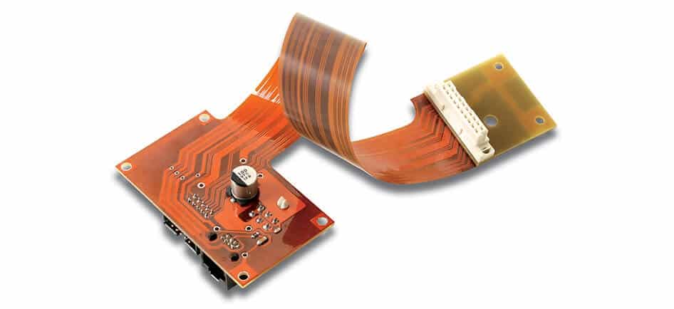
Flex PCB soldering has become increasingly popular in the electronics industry, primarily due to the growing need for compact, lightweight, and flexible electronic devices. With the shift from traditional rigid printed circuit boards (PCBs) to flexible PCBs, professionals must be aware of specific aspects when soldering surface-mount devices (SMDs) on these flexible materials.
Given the unique characteristics of flexible PCBs, SMD soldering presents a distinct set of challenges compared to soldering on rigid boards. To achieve successful solder joints on flex PCBs, it is crucial to pay attention to a few key factors that can significantly impact the reliability and performance of the electronic product.
In this article, we will discuss five essential factors to pay attention to when soldering SMDs onto flex PCBs. These factors will not only help you avoid common pitfalls but also ensure a seamless soldering experience and enhance the overall functionality of your electronic devices.
5 Key Factors to Consider When Soldering SMD on Flex PCB
Type of Solder
It is crucial to select the appropriate type of solder for flex PCBs. Some popular options include lead-free solder, leaded solder, and low temperature solder. Consider the melting point and the alloy composition, as these factors influence the solder’s performance and compatibility with your components.
Soldering Techniques
Select a soldering method based on your project requirements and level of experience. Common techniques include:
- Manual soldering
- Reflow soldering
- Wave soldering
For high-precision soldering, reflow soldering may be the best option. However, manual soldering could be more suitable for small-scale projects or prototypes.
Surface Preparation
Proper surface preparation is vital for optimal soldering results. Start by cleaning the flex PCB surface to remove dirt and contaminants. A commonly used method is applying isopropyl alcohol (IPA). Additionally, apply a suitable flux to improve solderability and prevent oxidation during the soldering process.
Component Placement
Accurate component placement is essential for a strong solder joint. Use a tweezers or a vacuum pickup tool to place the SMDs on the flex PCB carefully. Align the pads on the components with the pads on the PCB, ensuring all pins are correctly positioned and there are no misalignments.
Thermal Management
Flex PCBs are more sensitive to heat compared to rigid PCBs. Therefore, manage heat carefully during the soldering process to prevent damaging the flex material. Utilize a temperature-controlled soldering iron, preheat the PCB to avoid thermal shock, and use a proper heat sink if necessary.
Common SMD Soldering Challenges

Solder Bridging
Solder bridging is a common issue when soldering SMD components. It occurs when two or more adjacent pads are unintentionally joined by excess solder. This can lead to short circuits and poor electrical performance. To prevent solder bridging:
- Use the appropriate amount of solder paste
- Ensure accurate component placement
- Opt for a proper soldering iron tip size
Tombstoning
Tombstoning, also known as the Manhattan effect or drawbridging, is when a surface-mount component is raised on one end during the soldering process. This can result in a poor connection or complete disconnection. Factors that contribute to tombstoning include:
- Uneven heating during soldering
- Mismatched pad sizes or component dimensions
- Inconsistent solder paste application
To minimize tombstoning, consider implementing these strategies:
- Employ proper solder paste stenciling techniques
- Ensure uniform heating across the PCB
- Verify component and pad dimensions are compatible
Voiding
Voiding is the formation of empty spaces or voids within solder joints. These voids can negatively impact the thermal and electrical performance of the component. Common causes of voiding include:
- Excessive solder paste application
- Insufficient solder paste wetting
- Volatile elements trapped in the solder joint
To reduce voiding, consider the following approaches:
- Use an appropriate solder paste composition
- Optimize the solder paste printing process
- Implement a controlled soldering profile
Soldering Equipment Selection
Soldering Irons
When selecting a soldering iron for Flex PCB SMD soldering, consider the following factors:
- Wattage: Aim for a soldering iron with a wattage between 20W to 60W. This range provides adequate heat for most SMD soldering tasks.
- Temperature Control: Choose a soldering iron with temperature control for precise heat application. This ensures that you do not damage the sensitive components.
- Tip Selection: Look for soldering irons that support interchangeable tips. Different SMD components require specific tip shapes and sizes for proper soldering. Some common tips include:
- Chisel tip: for general soldering tasks
- Needlepoint tip: for precision soldering
- Conical tip: for surface mount components
Hot Air Rework Stations
For successful SMD soldering, consider investing in a hot air rework station. Here’s what to look for:
- Temperature Range: Aim for a hot air rework station that provides a wide and adjustable temperature range (100°C to 400°C), enabling you to work with various SMD components with different melting points.
- Airflow Control: Adjustable airflow control enables you to choose the right setting for each SMD component, providing a gentle stream of air for delicate components or a stronger airflow for larger solder joints.
- Nozzle Selection: Different tasks might require different nozzle sizes. Choose a hot air rework station with interchangeable nozzles, such as:
- Round nozzle: for evenly distributing heat over a larger area
- Bent nozzle: for reaching tight areas
- Needle nozzle: for precision heating of small components
Remember, selecting the appropriate soldering equipment is crucial for ensuring efficient and safe SMD soldering on Flex PCBs.
Safety and Protective Measures
Personal Protective Equipment
When working with Flex PCB soldering SMD, it’s essential to use proper personal protective equipment (PPE) to ensure your safety. Some recommended PPE items include:
- Safety glasses: Protect your eyes from soldering fumes and particles.
- Heat-resistant gloves: Protect your hands from burns when handling hot soldering irons or PCBs.
- A proper mask or respirator: Protect your respiratory system from harmful fumes released during the soldering process.
Proper Ventilation
Another crucial aspect of safety when soldering Flex PCBs is ensuring proper ventilation. Soldering can produce harmful fumes that can be hazardous to your health when inhaled. To minimize the risks, follow these steps:
- Work in a well-ventilated area: Make sure there is adequate airflow in your workspace. If possible, work near a window or install an exhaust fan.
- Use a fume extractor: A fume extractor will help remove harmful fumes generated during the soldering process, ensuring you are not exposed to them.
- Keep the soldering area clean: Regularly clean and maintain your workspace to reduce the buildup of fumes and other contaminants.
Inspection and Quality Control
Visual Inspection
Visual inspection is essential for identifying any noticeable defects in the flex PCB soldering. Inspectors should look for signs of misaligned components, solder bridges, missing components, and poor wetting. Fine-tip tweezers and magnifying equipment can help enhance the detection of these issues. When performing visual inspection, it is crucial to consider:
- Proper lighting conditions
- A systematic inspection approach
- Training and experience of inspectors
Automated Optical Inspection
Automated Optical Inspection (AOI) systems are widely used in the PCB assembly industry to detect soldering issues and component placement errors automatically. Some key benefits of the AOI system include:
- High-speed inspection
- Enhanced defect detection
- Consistent, reliable results
- Capability to inspect fine-pitch components
During AOI, the machine compares the inspected flex PCB panel with a reference image, which is typically a known good sample, allowing for accurate detection of defects and soldering issues.
X-ray Inspection
X-ray inspection plays a vital role in the quality control process of flex PCB soldering, particularly for detecting issues in hidden solder joints, which are difficult to observe through visual or AOI methods. X-ray inspection can reveal:
- Insufficient or excess solder
- Broken or weak solder joints
- Void detection within soldering pads
- Incorrect component placements
Using X-ray inspection systems, manufacturers can identify these issues early in the production process and maintain a high level of quality control for flex PCB soldering SMD assemblies.
