With the advent of digital manufacturing and the new PCB technology, a new type of board came into the market. The Veroboard is a more compact version of the traditional breadboard. It has many advantages over traditional PCBs. As a result, we sometimes refer to it as matrix board or stripboard.
It is easier to build and use than a traditional breadboard. We can use it with any number of components, not just 2 or 3 pins like the breadboard. Assembling can happen in seconds instead of minutes, compared to hours for breadboarding. And it is much cheaper than any other board solution out there. You can manufacture using the Epoxy-based substrate or copper-clad laminate board.
Vero board is one of the most widely used type of PCB layout software. It is a free and open-source broad-spectrum PCB layout software that caters to the needs of various manufacturers and users. With Vero, you can create your PCBs using their standard components. The software uses schematic markup language (MSML) as its schematic diagramming tool. It supports all the popular vendor designs, such as Gerber, EAGLE, Asenavar, and many more. You can also import schematics from third-party design tools such as KiCad or Eagle CAD for easier design reuse. This article will give you a deeper understanding about Vero board and its working principle, what makes them different from breadboards, and how they can benefit your project.
What Is a Vero Board in PCB Design?
If you’re planning on making a circuit board, you’ve probably heard about Vero Board. But what exactly is it? And what is its use?
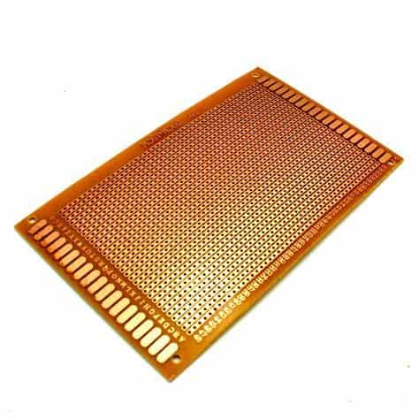
The veroboard or stripboard is a general-purpose PCB. It has 2.54mm regular grid rectangular holes, parallel copper cladding running strips in one direction across the board’s single side.
Vero Board is a good choice for development and prototyping work because it is ideal for hard wiring discrete components. In addition, this type of board is typically useful for analogue circuits and circuits that use common bus lines. The material used for Vero boards comes from a copper-clad laminated board pierced with a grid of holes. It can also be cut to size.
Another way to design with a Vero board is to use a de-solder braid as a substitute for solder. For longer cuts, you can use a vice. A round needle file is also useful. Flush cut snips are useful for cutting links and long leads. You can also use a curved scalpel to cut copper tracks. Finally, you can use a metal ruler and a hard metal straight edge to score the Veroboard before soldering.
Veroboards are also ideal for beginners who are interested in electronics. They contain holes that are tenths of an inch apart, allowing most standard through-mount components to fit. The holes are also connected to each other electrically.
Vero Board Types
There are several types of Vero boards, each with a different function. Depending on the board type, Vero will have various options for the layout and the connections. These options can be useful for both breadboard prototyping and finished Veroboard designs. In addition, such boards can handle a wide range of input voltages and accommodate a variety of component configurations.
Vero boards are characterized by small holes and a grid of copper dots. They’re usually cheaper than traditional circuit boards, and are a great solution for prototypes and low-volume production. However, they’re not good for final products, high-vibration areas, or high-voltage objects. Hence, Vero boards are best for smaller circuits, requiring only a few components.
Rigid PCBs, on the other hand, are made from copper trances and a glass fiber substrate. These layers make the board firm, reducing the need for soldering. In addition, the copper layer is covered by a solder mask layer, which minimizes the risk of damage. Finally, the outermost layer of the rigid PCB is made of silkscreen. This silkscreen carries symbols and characters.
Stripboard is another type of PCB. Sometimes referred to as Vero boards in the UK, Stripboard is a good choice for prototypes or functional circuit boards. This type of board has 0.1-inch grid holes and copper parallel strips on one side. This type of board is ideal for prototyping, as you can add or remove components easily.
Vero Board VS. Breadboard
Vero board is a general-purpose prototyping board that resembles a PCB but has a large number of small holes and copper dots. These holes allow you to solder components on it and build circuits. You can use wires to undertake routing in the desired direction. Breadboards also have spring terminals, making it easy to insert wires and create circuits. No need for soldering in breadboards.
Printed circuit boards are more versatile and durable than breadboards. Compared to breadboards, PCBs have high current carrying capabilities. They can also be useful for exterior linking, unlike breadboards. Furthermore, printed circuit boards have a clean and professional look compared to breadboards.
The breadboard’s name comes from the early days of electronics. Back then, people used to hammer nails and screws into wood boards to connect circuits. Today, there is no need to hammer or damage your cutting boards for your electronics projects. However, you will still need to make a breadboard before you can move on to a permanent circuit board. This way, you can connect different components without damaging your cutting boards.
A Vero Board is an alternative to a breadboard. It mimics a breadboard’s layout and is easy to use for making quick changes and repairs. The Vero board is a good choice for your first few boards. After that, it’s easy to make changes and fixes and quick and easy to set everything up right the first time.
The Uses of the Vero Board
Veroboards are good in making small, low-power circuits. They are also a good choice if you’re working on a limited budget. They have numerous features, such as diode protection, load regulation, smoothing caps, and 2.1mm jacks for power. In addition, these boards don’t take up as much space as a dedicated PCB.
Veroboard circuit design is simple, and you can do it in several ways. One of the methods is to draw the circuit from above. Start by choosing the component with the most pin outs (most pin-dense IC), for example, the 8-pin 555 timer IC. Next, start with the pin out at the top left and draw from there. When finished, the pin should be on the center of your graph paper. For example, a DIL socket has two rows of pins, separated by three inches.
Vero boards are similar to plug-in breadboards, but they’re more permanent. They’re cheaper and require soldering, but you can reuse them a number of times. However, they’re not suitable for physical mock-ups of working circuits. They are also not recommended for environments with vibration.
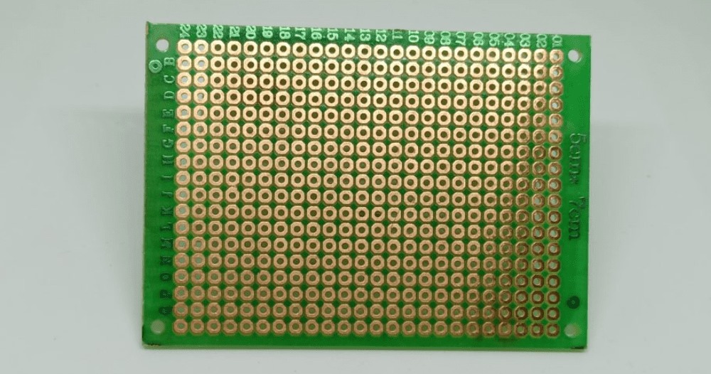
Veroboards are generally useful for general-purpose PCBs. The Veroboard’s 2.54mm grid of holes is commonly used for this purpose. It also has parallel strips of copper cladding on one side. Its features make it popular among beginners and hobbyists alike.
Veroboard Design Software
The Veroboard design software enables users to create and edit PCBs. The software provides various features essential for PCB creation, including an easy-to-use interface, a library of components, and support for perforated circuit boards. Users can use the software to create circuits, arrange components by pin number, and add trace cuts and shorts. They can also print component locator labels and export their designs as net lists, which are useful for commercial PCB packages.
The Veroboard design software is compatible with most operating systems, including Windows, Linux, and Mac OS. It can create single-sided and multi-sided PCB layouts, and support board sizes up to 70 holes by 70 tracks. It also allows users to easily mark the components and break circuits. In addition, the software allows users to view both sides of a circuit, which can be helpful when placing track breaks. The software also allows users to produce a Bill of Materials and a PNG image of their circuit.
Altium Designer also includes advanced routing features making it simple to design and produce BGA fanouts for advanced products. Its comprehensive routing features work alongside standard schematic editor and schematic capture features, so users don’t need to use another program to complete layouts.
Components of the Veroboard
The Veroboard consists of several components. You connect these components to the circuit by soldering through the holes. Some are polarized, so you should mark them accordingly on the design. Others, such as the battery, power supply, and LED, should be marked on the design.
When designing a board, consider the size of the components. For example, the mechanical unit may require a board with a large area, while a small board with outside connectors will be enough for a small integrated circuit. Large integrated circuits require more room to break signals and separate components. Consider using a pre-set board size or shape if space is an issue. Such can save you time and money.
If you’re considering the Veroboard as a PCB material, you’ll want to think about how to place your components. In general, the Veroboard pitch is 2.54mm, which implies that the holes on the board are 2.54mm wide. High-density applications will generally require fine-pitch components. However, these components may also require more expensive equipment and x-ray inspection.
Vero Board Manufacturer and Shipping Information
If you are looking for a Vero board manufacturer, you will want to consider a few things before you make your purchase. These factors include Ship and delivery times, Copper cladding running, and original packaging. Then, you’ll want to look into the Vero board sizes you need.
Ship and delivery times
The delivery time depends on the destination. Generally, it takes three to four days. However, there are times when delivery can delay. In such cases, you get a notification via email. Shipping costs vary based on destination. To get a better idea of shipping costs, you can use an international shipping estimator.
Copper Cladding Running
You can make Vero Board from copper cladding. We can apply them in a variety of applications, including film preproduction. This copper cladding is usually available in large sheets, which is more cost-effective per square foot. The process of cutting this material requires a steel ruler and a Stanley knife. Hold the knife against the copper side of the board.
The Vero Board contains 2.54mm-wide, parallel strips of copper cladding running down one side of the board. This material is ideal for prototyping projects and for beginner circuit designers and hobbyists alike. The strips are perforated with holes that allow you to solder components.
Prototype Boards
Vero boards are a great way to prototype electronic circuits for electronics manufacturing. You can test individual components on a Vero board and get an idea of how they work before you start fabricating the complete PCB. However, if you are looking for a more reliable PCB, choose a vero board. This PCB allows you to automate the component placement and is generally more reliable.
When designing prototypes, it is important to understand the material requirements. This can vary depending on the work you will do with the prototype. Generally, the material must be standard and be able to withstand high temperatures. In some cases, flame-retardant materials are necessary.
How to Design a Circuit Using Vero Board in PCB
When designing a circuit using the Vero Board, it is important to label components and wires correctly. For example, mark the LED, battery, and power supply on the Vero Board. Also, note which pins of the IC are polarized. You can also draw the circuit links using a highlighter pen.
Consider this if you are working with simple, low-power circuits and on a budget. This option allows you to use the Veroboard for breadboard prototyping, and it also incorporates diode protection, load regulation, and smoothing caps. The breadboard option also uses a 2.1mm jack for the power supply and accepts a wide range of input voltages.
The Vero Board is an excellent choice for many projects. It is composed of high-quality phenolic material and has copper rows plated with tin. This board is also great for testing and adding add-ons to your circuit. It’s also easy to cut and use in many applications.
