Altium, a leading provider of PCB design software, has recently released a new guidebook on rigid-flex design. The guidebook is a comprehensive resource for engineers and PCB designers who are looking to design and manufacture rigid-flex PCBs.
Rigid-flex PCBs are becoming increasingly popular due to their ability to combine the benefits of both rigid and flexible PCBs. They are ideal for applications where space is limited, and where the PCB needs to be able to bend or flex. However, designing and manufacturing rigid-flex PCBs can be a complex and challenging process. The Altium Rigid-Flex Guidebook aims to simplify this process by providing a step-by-step guide to designing and manufacturing rigid-flex PCBs using Altium Designer.
Overview
What is Altium Rigid Flex?
Altium Rigid Flex is a design tool that helps engineers create printed circuit boards (PCBs) that incorporate both rigid and flexible materials. This allows for greater design flexibility and can be especially useful in applications where space is limited or where the PCB needs to conform to a specific shape or surface.
Why Use Altium Rigid Flex?
Altium Rigid Flex is a powerful tool for PCB design that offers a number of benefits over traditional rigid PCBs. One of the main advantages is the ability to create more complex designs that can incorporate both rigid and flexible materials. This can help reduce the size of the PCB, which can be especially important in applications where space is at a premium.
Another advantage of Altium Rigid Flex is that it can help reduce the number of components needed in a design. This can help simplify the manufacturing process and reduce the overall cost of the project.
Benefits of Altium Rigid Flex
There are several benefits to using Altium Rigid Flex for PCB design. Some of the key advantages include:
- Greater design flexibility
- Reduced size and weight
- Improved reliability and durability
- Simplified manufacturing process
- Reduced cost
Altium Rigid Flex is a powerful tool that can help engineers create more complex and efficient PCB designs. With its ability to incorporate both rigid and flexible materials, it offers greater design flexibility and can help reduce the size and weight of the final product. Additionally, Altium Rigid Flex can help simplify the manufacturing process and reduce overall costs.
Design Considerations

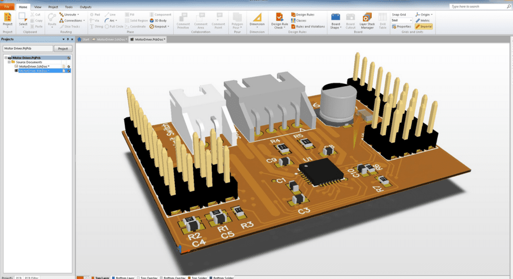
Stackup Design
The stackup design is an essential factor when designing a rigid-flex PCB. The stackup should be designed to meet the electrical and mechanical requirements of the product. The stackup should also be optimized for signal integrity and power integrity. The following table shows an example of a typical 6-layer rigid-flex stackup.
| Layer | Material | Thickness (mil) |
|---|---|---|
| 1 | Top Copper | 1 oz |
| 2 | Prepreg | 2 mil |
| 3 | Core | 4 mil |
| 4 | Prepreg | 2 mil |
| 5 | Bottom Copper | 1 oz |
| 6 | Coverlay | 1 mil |
Component Placement
Component placement is another critical factor in the design of a rigid-flex PCB. The placement of components should be optimized to minimize stress on the flex circuit. The following guidelines should be followed when placing components on the flex circuit:
- Place components on the rigid sections of the board whenever possible.
- Avoid placing components near the bend areas of the flex circuit.
- Minimize the number of vias on the flex circuit.
Routing Guidelines
Routing guidelines are essential in the design of a rigid-flex PCB. The following guidelines should be followed when routing a rigid-flex PCB:
- Route signals on the rigid sections of the board whenever possible.
- Avoid routing signals on the bend areas of the flex circuit.
- Minimize the number of vias on the flex circuit.
- Use teardrops to reduce stress on the flex circuit.
By following these design considerations, you can ensure that your rigid-flex PCB meets the electrical and mechanical requirements of the product.
Fabrication
When it comes to fabricating a rigid-flex PCB, there are several key considerations that must be taken into account. These include material selection, panelization, drilling, and plating.
Material Selection
Choosing the right materials for a rigid-flex PCB is critical to ensuring its long-term reliability and functionality. Some of the most commonly used materials for rigid-flex PCBs include polyimide, FR-4, and copper. Each of these materials has its own unique properties and advantages, so it’s important to carefully consider which one is best suited to your specific application.
Panelization
Panelization is the process of arranging multiple PCBs on a single panel for ease of production. When it comes to rigid-flex PCBs, panelization is particularly important, as it can help minimize the risk of damage during the fabrication process. Additionally, panelization can help reduce the overall cost of production by allowing for more efficient use of materials.
Drilling
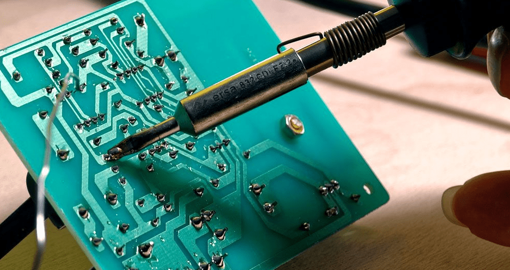
Drilling is a critical step in the fabrication process, as it is used to create the holes that will be used for component placement and electrical connections. When drilling a rigid-flex PCB, it’s important to use the right tools and techniques to ensure that the holes are properly aligned and sized. Additionally, it’s important to take steps to prevent burrs and other defects that can impact the overall quality of the finished product.
Plating
Plating is the process of adding a thin layer of metal to the surface of a PCB to improve its conductivity and durability. When plating a rigid-flex PCB, it’s important to use the right materials and techniques to ensure that the plating is even and consistent across the entire surface of the board. Additionally, it’s important to take steps to prevent defects such as voids and delamination, which can compromise the overall quality of the finished product.
Assembly
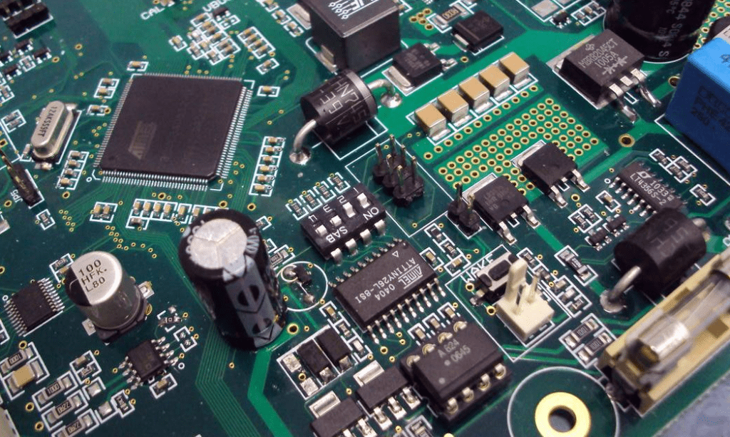
When it comes to assembling rigid-flex PCBs, there are two main methods: Surface Mount Technology (SMT) and Plated Through Hole (PTH) assembly.
SMT Assembly
SMT assembly involves placing and soldering surface mount components directly onto the PCB’s surface. This method is ideal for small components, as it allows for a higher component density and better signal integrity. It is also a faster and more cost-effective method of assembly compared to PTH.
To ensure a successful SMT assembly, it is important to consider the following factors:
-
Component placement: Proper placement of components is crucial to ensure that the assembly process goes smoothly. It is important to ensure that components are placed in the correct orientation and at the correct distance from each other.
-
Solder paste: The correct amount of solder paste should be applied to each pad to ensure a strong and reliable joint. It is important to use the correct solder paste for the specific components being used.
-
Reflow profile: The reflow profile should be optimized for the specific PCB being assembled to ensure that the solder paste melts and reflows correctly.
PTH Assembly
PTH assembly involves inserting components through holes drilled in the PCB and then soldering them in place. This method is ideal for larger components, as it provides a stronger mechanical connection and better heat dissipation. However, it is a slower and more expensive method of assembly compared to SMT.
To ensure a successful PTH assembly, it is important to consider the following factors:
-
Hole size and placement: The size and placement of the holes should be optimized for the specific components being used to ensure a strong mechanical connection.
-
Component insertion: Components should be inserted into the holes with the correct orientation and at the correct depth.
-
Soldering: The correct amount of solder should be applied to each joint to ensure a strong and reliable connection. It is important to use the correct solder for the specific components being used.
In conclusion, both SMT and PTH assembly methods have their advantages and disadvantages. Choosing the right method depends on the specific requirements of the PCB being assembled.
Testing and Inspection
Electrical Testing
Before the final assembly, electrical testing is conducted to ensure that the rigid-flex design works as intended. Different types of tests are carried out to ensure that the electrical connections are solid and reliable. These tests include:
-
Continuity Testing: This test checks the continuity of the electrical connections between the different layers of the rigid-flex PCB. It ensures that there is no break in the electrical path.
-
Impedance Testing: This test checks the impedance of the signal traces and ensures that the signal integrity is maintained throughout the PCB.
-
High Voltage Testing: This test checks the insulation between the different layers of the rigid-flex PCB. It ensures that there is no short circuit or leakage in the electrical path.
Visual Inspection
Visual inspection is carried out after the electrical testing to ensure that there are no defects or issues with the rigid-flex PCB. The inspection includes:
-
Soldering Inspection: This inspection checks the quality of the soldering joints. It ensures that there are no cold solder joints, solder bridges, or other issues that could cause problems.
-
Component Inspection: This inspection checks the placement and orientation of the components. It ensures that the components are correctly placed and oriented as per the design.
-
Trace Inspection: This inspection checks the quality of the traces. It ensures that there are no scratches, cracks, or other defects that could cause problems.
Overall, testing and inspection are critical steps in the manufacturing process of rigid-flex PCBs. They ensure that the PCBs are reliable and free from defects.
