For building, constructors must develop a plan to carry out construction in a particular order and using specific materials. Typically, they begin construction by building a concrete foundation and then move on to the wood or steel framing, then a floor, and finally the building’s roof. Likewise, PCB manufacturers must utilize a plan and a couple of materials to develop the Printed Circuit Board Materials that you find on electronics such as laptops and TVs.
A bit about PCB Fabrication
To carry out PCB fabrication, manufacturers utilize silkscreen, laminate, a substrate, and solder mask, among other materials, to complete the process. The silkscreen layer, usually on the top part of the PCB, is utilized for identification. Technicians apply invaluable marking on these material making PCBs easy to use when constructing electronics. On the other hand, Solder masks act as protective layers for a PCB. After application, this material shields Printed Circuit Boards against contamination. Moreover, these material also provides isolation between different surface elements such as drill holes, copper traces, and pads.
On the other hand, your PCB’s foundation integrity rounds up to the type of laminate and substrate you utilize. Therefore, when you use a lousy substrate or a bad laminate, your PCB will be bad, and vice versa. Therefore, to avoid constructing lousy PCBs, you should know how to choose the best Printed Circuit Board components on the market today.
Printed Circuit Board Materials
Your PCB’s foundation (base) comprises a laminate and a core (substrate). The core is typically a non-conductive dielectric component that technicians choose depending upon the PCB’s dielectric constant (dk).
Technicians then utilize the substrate with a laminate to generate a surface material or a copper foil. However, in exceptional cases, technicians may decide to use the laminate as the PCB’s core. It all narrows down to how technicians are looking to utilize the PCB.
Substrates
A substrate is typically a dielectric component that comprises of epoxy resin and glass weave or paper. However, some technicians might also opt to utilize an unwoven glass to substitute the glass weave.
Building this component is not straightforward since technicians have to consider many things. For starters, they have to consider the material’s Tg (the glass transition temperature), which is usually the temperature at which the materials start to soften or deform. Therefore, when building PCB to function under high temperatures, they must customize the board’s Tg for it to work effectively. Also, to boost the board’s dielectric constant, technicians utilize ceramics to supplement the substrate. Doing so makes the board efficient and more durable.
Due to these alterations and customization issues, many substrate standards exist that you can utilize to fabricate your PCB. These substrates include, insulated metal substrate, Polytetrafluoroethylene (PTFE), Alumina, Kapton, Pyralux, G-10, G-11, FR-1 to FR-6 and CEM -1 to CEM -5. However, out of all these PCB substrates, technicians mostly prefer to utilize FR-4.
Laminates
Laminates typically consist of a thermoset epoxy resin and paper and cloth layers. To manufacture this component, manufacturers apply pressure onto these materials, and the components turn into a laminate. However, like substrates, technicians can also customize laminates to meet the needs of certain PCBs for example those that utilize surface mount technology. However, when dealing with laminates, the points to consider include, Shear strength, Tensile, Coefficient of Thermal expansion, Tg and CTE. On the other hand, the dielectrics that technicians mainly utilize for laminates typically include, Teflon (polytetrafluoroethylene), CEM-3, CEM-1, FR-4 and FR-1
The best Laminates to use on your Printed Circuit Board
A laminate is a crucial aspect to keep in mind when looking for the perfect materials to utilize on your PCB. Therefore, here are the most popular laminates in the market today and why they are pretty common:
FR4 prepreg and Epoxy Laminate
By far, FR4 laminate is the most utilized Printed circuit Board laminate worldwide. FR4 is a denotation that describes a category or a class of components that meet specific NEMA LI1-1998 standard requirements.
Why are FR4 laminates pretty popular in the market today?
FR4 components have excellent mechanical, electrical, and thermal properties. What’s more, these components also have an ideal weight-to-strength ratio, which makes them great for a majority of electronic components application. These laminates are also cost-effective, which makes them the first choice for technicians looking to build a high-quality, cost-effective PCB. FR4 laminates are pretty popular for Printed Circuit Boards that do not have many layers; this includes, Singles sided PCBs, Double-sided PCBs and Multilayer PCBs (that do not exceed 14 PCB layers).
Additionally, you can blend various additives into your FR4 laminate to boost its electrical and thermal performance. Due to this feature, technicians do not have a hard time developing custom FR4 laminates for various clients. Moreover, this feature also improves the laminate’s UL frame rating, which in turn helps boost the amount of layer that this laminate can handle. FR4 prepregs and laminates are pretty adaptable and versatile. Moreover, they also bear multiple manufacturing techniques, making the PCB assembly phase that much easier to handle.
Polyimide Prepreg and Laminate
Polyimide laminates provide a higher temp performance when you compare them to FR4, which makes them the second most popular laminates in the market. What’s more, these laminates also have slightly better electrical properties.
However, regarding price, polyimide laminates tend to be more expensive than FR4 laminates. But this cost difference is justified by the fact that polyimide laminates provide better survivability percentages when PCBs are functioning under harsh conditions. Moreover, a rigid PCB that utilize polyimide tends to bear a thermal cycle that is more stable which makes it more predictable and hence manageable.
Teflon Bonding Piles and Laminates
Teflon bonding piles and laminates provide impeccable electrical properties, making them great for constructing high-speed PCBs and electrical components. However, compared to polyimide components, Teflon components cost more money. But in the long run, PCB designers get their money’s worth as they generate PCBs that bear impeccable speeds.
When working with Teflon materials, the manufacturer can choose to coat the component onto a glass fabric. However, they can also manufacture the component as a film (unsupported) or with it bearing unique additives and fillers to boost its mechanical properties.
Why are Teflon bonding Piles and Laminates not that popular?
Teflon PCBs’ production process requires technicians with exceptional skills and unique equipment. What’s more, this production process tends to yield fewer PCBs.
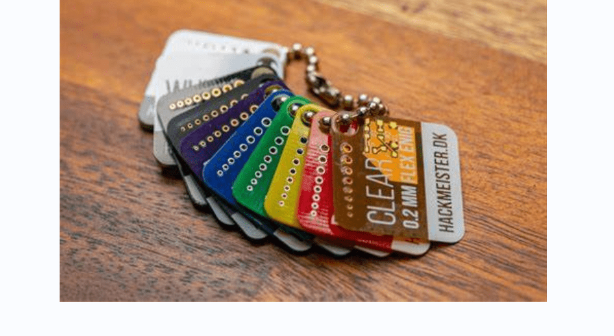
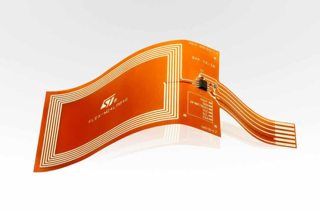
Flexible Laminates
Flex laminates are usually pretty thin and typically help technicians develop flexible PCBs that can fold without snapping or breaking the current’s flow. Moreover, these laminates also play a huge part in the development of rigid flex boards.
These laminates do not bear a glass fabric that helps support a PCB and makes it turgid. Instead, they are built on a plastic film, boosting their flexibility even more.
You can develop a flex laminate system using high-temperature components like LCP (liquid crystal polymer) and polyimide. However, this option tends to cost you a lot as the materials are expensive. On the other hand, you can opt to go with the cheaper option, which involves utilizing low-cost components, for example, PEN and polyester.
Why are Flexible Laminates not that common?
Since flex PCBs are pretty thin and flexible, they often require skilled technicians to develop lean and flexible circuits (flex circuits). These technicians must also utilize unique processes and equipment to get the job done. Due to the complexity of this production process, you should ultimately anticipate low yields.
Together, substrate and laminate materials define the mechanical, thermal, and electrical properties of your Printed Circuit Board. Therefore, these are essential components to remember when looking for PCB materials to build your Circuit Board. However, to make the best substrate layer and laminate materials selection, you must have the right board type in mind. These three properties go hand in hand.
Types of Printed Circuit Boards
Printed Circuit Boards fall under a couple of categories which include:
Component Location
In this category, you will find embedded, double-sided and single-sided PCBs.
Stack up
Stack-up PCBs typically include Printed circuit boards such as a Single layer PCBs and Multiple layers PCBs. Under this category, multi layer PCBs tend to be more complex to construct.
Design
Under this category, you will find Custom-special PCB and Module-based PCBs.
Bendability
The bendability or Flexible category of PCBs comprises of Rigid circuit boards, flex and Rigid Flex PCBs.
Strength
Under the strength category, we have the PCBs that are electrically strong and PCBs that are mechanically strong
Electrical Functionality
Under this category, we have, Microwave PCBs, High-density PCBs, High Power PCBs, and High-Frequency PCBs.
These are the PCB types that exist in the market today. However, when choosing material for your Printed Circuit Board, you should not pay much attention to the first three categories. That is because these properties do not have much to do with the PCB materials you utilize to make your Circuit Board.
Also, while strength and bendability are great options to consider when looking at your board’s physical properties, these two don’t provide proper guidance regarding your board’s functionality. On the other hand, Electrical functionality affects how your Printed Circuit Board functions. Hence you should significantly consider this property.
To make this task easier, let us classify PCBs according to how they function.
PCB Classification according to Functionality
High Frequency or High-Speed PCBs
For a board to fall under this category, it has to accommodate high frequencies that range between 500MHz to 2GHz.
High Power PCBs
High Power PCBs are PCBs that can easily transport high currents without burning out or short-circuiting. These types of PCB typically require thicker copper layers and broader circuit traces. They must also be able to dissipate heat and withstand high temperatures without a hassle.
High-Density PCBs
High-density PCBs are typically more complex when you compare them to other PCBs. These PCBs have pretty thin traces, which helps them accommodate a pretty dense copper circuitry. Moreover, they also utilize slim, high-performance components and laser microvias to save on space, making them pretty compact but also efficient.
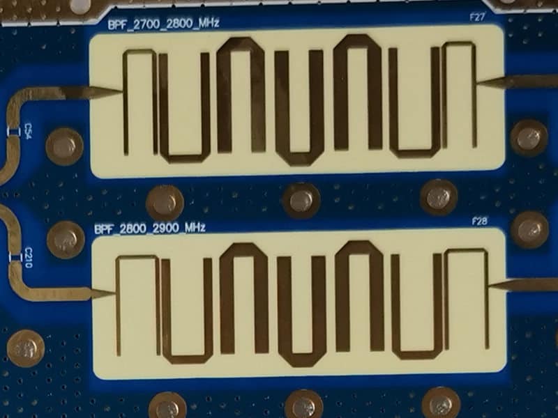
Microwave PCBs
Microwave PCBs are typically PCBs that can handle high speed signals that hit 1GHz and above. However, even though these PCB go by the name microwave, it would be good for you to note that microwaves tend to have a frequency range that fall between 1GHz and 1000GHz.
With these board types in mind, you can easily select the best Printed Circuit Board material for your Printed Circuit Board.
Printed Circuit Board Solder Mask
Most Printed Circuit Boards typically come in one color variation, green. However, this green color is not due to some technicians applying green colors to a PCB. Instead, the green color is visible due to the presence of the solder mask. Actually, this is the color of the solder mask.
However, though not that common, solder masks tend to sometimes appear in varying colors, for example, blue or red.
Solder mask has one functionality on PCBs. They shield Printed Circuit Boards against liquid solder leakage.
After the application of the solder mask, technicians move on to the next stage, which is the application of molten solder. During this phase, the exposed copper layer become solderized; through a process commonly known as HASL (hot air solder leveling). Without solder mask application, solderization would typically ruin a PCB. However, with a solder mask in place, technicians can develop complex circuits without breaking a sweat. Therefore you should highly consider the type of solder mask you utilize for your PCB.
How does PCB Material Selection Affect the Cost of PCB Manufacturing?
When it comes to Printed Wiring Boards, you will find that the price is directly proportional to the types of features it contains. Therefore, if you choose to utilize golden tabs, or buried vias, the amount of money you will spend on your Printed Wiring Board will automatically be high. Likewise, Printed Circuit Boards that bear width/line spacing below six mils tend to be expensive.
The reason behind this phenomenon is simply the PCB manufacturing process complexity. That is because PCBs with small width spacing require great accuracy and precision. However, those with a broader line spacing do not require as much precision, making them easy to manufacture.
Therefore, if you are looking to build a cost-friendly PCB, you should also consider the price of the components you utilize and other factors, such as line spacing and copper thickness.
Conclusion
PCB fabrication is a complex process that requires technicians to utilize unique components to get it right. However, using the components we have gone through, you can replicate this process and produce cost-effective, high-quality PCBs without breaking a sweat.
