There are a variety of methods for making PCBs. There are a few steps involved in making a board that really works. PCB designs are the initial stage in the fabrication process. A vital part of making PCBs is the design phase.
There is a wide variety of PCB design tools available. The PCB web designer, Eagle, and Proteus are all a part of this. Schematic design and PCB design are both areas where PCB design software could use some refinement.
Proteus, the PCB design software, provides various samples. Last but not least, our attention is fixed squarely on that essay in Proteus. Let’s talk about printing circuit boards in Proteus.
Types of PCB Based on PCB Design
PCBs come in two different shapes. These include PCB layouts and dots.
Dotted PCBs
The top surface of a dotted PCB is covered in dots. Additionally, this professional PCB design is feasible to insert components within the holes themselves. After that, the creator of the computer software will add components using wire, and then they will solder it. Because of the prevalence of faults, dotted PCBs are notoriously difficult to design.
Layouts PCBs
Designing and putting together the board layout is a simple process. The computer engineers developed the software that was used in the construction of this circuit. After that, a design engineer enclosed the components and soldered them into a printed circuit board (PCB). Because there is less room for error in the manufacturing process, printed circuit boards (PCBs) are easier to design.
What is Proteus?
The primary functions of the Proteus PCB program are the generation of schematics and the design of printed circuit boards. This PCB design software combines the PCB layout module with schematic capture to provide an easy-to-use yet sophisticated set of tools for the creation of PCBs
With all of the options at your disposal, creating PCBs has never been easier than with this program. The program known as Proteus comes with a robust and comprehensive integrated development environment. The tools included in Proteus are perfect for carrying out professional-grade schematic capture and PCB design. In addition to that, utilizing any of these tools is a breeze.
The space-based auto router is one of the professional PCB design tools offered by this program. A fully complete schematic capture, an interactive SPICE circuit stimulator, and highly programmable design guidelines are some of the other fantastic features available. The Proteus PCB design program has comprehensive support for power planes as well as an integrated 3D viewer.
In addition, this PCB design software is an excellent choice for creating an up-to-date PCB layout. More than 25 years of continuous invention and product development have gone into Proteus. This PCB design software has been able to incorporate more powerful tools as a direct result of this fact.
The primary focus of Proteus development is on enhancing the software’s capabilities while preserving its intuitive user interface. Additionally, a strong connection with PCB schematic design is a primary emphasis of this program.
Both Proteus ARES and Proteus ISI are types of PCB layout programs that are included in the Proteus suite of products. The primary purpose for which Proteus ARES was developed was to direct the sequencing of printed circuit boards (PCBs) and the positioning of components.
Furthermore, the Proteus design suite includes a PCB design starter kit for novices. Users have a significant deal of design flexibility at their disposal using Proteus’s tools.

Advanced Features and Capabilities of Proteus
There are several options included in Proteus that you may use to create your PCB. The truth is a PCB designer has it much simpler because of these characteristics that simplify the final circuit board design. In addition, the fact that Proteus provides users with design tools makes it an excellent option for board design.
Footprint Library
The libraries provide coverage for a comprehensive range of through hole components. This encompasses the most popular types of transistors, integrated circuits, and diodes. Additionally, Proteus provides SMT footprints in addition to complete IEC library support. Standard surface mount library formats IPC-7351 and IPC-782 are also included in this software package.
Additionally, if necessary, you are able to build new packages on the drawing. The Proteus platform offers functionality for 2D drafting. The PADS ASCII circuit layout format may be imported directly using this program’s direct import function. Because of this, it is now possible for you to import footprints created by widely used programs such as Ultra-Librarian.
Hand Configured Path Finding
Manual routing allows you to skip the rats’ nest and go straight to the meat of the matter. Location tracking is also quite flexible and may be set up in whatever you like.
As the interconnections solidify, Proteus will assist you in eliminating the resulting rat’s nest of lines. When laying down a track, the path will follow the mouse’s movements and avoid obstructions.
When making changes to routes, you have the option to remove or reroute any segment of the route. In addition, there are options to modify the tracking layer for a specific region. With thick tracks between IC pads and other barriers, the path will naturally narrow at the bottlenecks.
As a result, you’ll be able to stick to the guidelines of the design better. Furthermore, laying down curving tracks is as easy as hitting the CONTROL key and dragging the mouse.
Specifications and Technological Formats
PCB layout is a part of Proteus, and it includes a comprehensive plan for the reuse of previous designs. This plan is also presented in a technological data format and a basic layout template. It’s up to you, the user, to create a set of pre-made examples for typical types of projects.
The board layout template may then be used as a jumping off point for future designs. As a result, you’ll be able to preload all the settings and configurations.
A template file consists of a generic format and a collection of technical specifications. Additionally, grids, design guidelines, and other elements are included in this data.
This information is transferable to other designs immediately.
Power Planes
The Proteus PCB software offers support for the ultimate power plane. In addition to this, there is a user-placeable polygonal region that is responsible for the development of inner borders around the already existing pads and tracking.
Once you make changes to the tracking and pads, the boundaries will need to be recalculated to verify that design rule clearances are met. Additionally, support for thermal relief is included in Proteus. Therefore, you have the option of hatching or filling each polygon on the map.
On Proteus, all computations follow a form geometry without a grid. This computation is also now taking place in the background. As a result, for setups that demand a lot of computing power, there won’t be any interference with the positioning of the manual board.
One of the more complicated aspects that may be specified by the Proteus PCB software is the placement of several power planes for each layer. In addition to this, in order to accomplish this goal you will require the Proteus PCB design Level 2 software.
Printed Circuit Board Design and 3D Visualization
A 3D visualization tool that allows you to extrude a PCB layout is one of the features offered by the Proteus PCB software. The ability to visualize data in three dimensions is one of the more sophisticated functions offered by Proteus.
A further benefit of this function is that it enables you to examine the board as it would appear in the real world. During the PCB designing process, this function is quite helpful. The navigation is fairly easy to understand and is managed with the mouse.
In addition to this, the user has the ability to create a “height pane” that corresponds to the board chassis. This will show up as a box surrounding the board, making it possible to visually inspect it for any protrusions.
Additionally, the Proteus PCB software has functionality for building bespoke 3D footprints in addition to its own 3D footprints. You may export files in these formats using the vast majority of commercial MCAD applications in addition to a broad variety of free resources available on the internet.
Stitching and Shielding
Through the use of stitching, bigger copper traces may be connected to one another on several layers. As a result, this contributes to the maintenance of short return routes and the reduction of noise on the circuit board.
A straightforward command in the context menu may also be used to automatically sew together aircraft. As a result, this grants you control over the manner in which you present yourself.
In a similar manner, you may either incorporate a picket fence or a shield around the perimeter of the aircraft. A result, this will result in the formation of a single row of vias all the way around the zone’s perimeter.
Additionally, this may aid in the prevention of EMI with other pieces of equipment. This method is perfect for isolating signals on the board that is running at a variety of frequencies, thus it may be used for high-speed lines.
Benefits of Using Proteus PCB Design Software
Without the proper tools, designing PCBs is a laborious process. The ideal program will include complex simulation tools that will aid in creating high-quality designs. Errors in PCB layout can be expensive to fix, thus it’s important to use reliable tools. Proteus, as software for creating circuit boards, has several advantages. Examples of these advantages are:
Intense Help
Even circuit board design software might have flaws due to its software nature. Proteus provides consumers with access to specialized software assistance. In addition, there are a number of user assistance options available. In the event that you run into any issues while using this program, you may reach out to the creators for assistance.
Excellent Value for the Money
Proteus is a reasonably priced program with top-notch functionality. When creating a PCB, designers frequently think about how much money they have to spend on the software. There are free internet design programs, but their usefulness and quality vary widely.
Convenience of Usage
You may count on this as a perk of using Proteus. Proteus’s user interface is intuitive. It’s a tool that can be used by anybody from amateurs to expert designers to students. The makers of this program have simplified certain graphical elements to make them more accessible.
Alterations and Enhancements
Every iteration of high-quality circuit board design software should be an improvement over the last. Not only that but Proteus is constantly updated with new and improved features.
How to Design a Printed Circuit Board Using Proteus
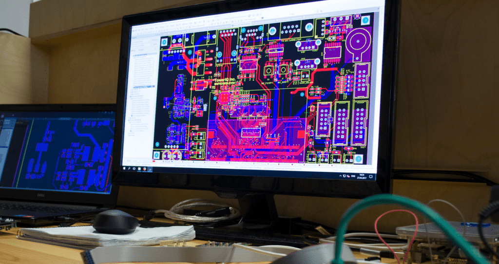
Virtual PCB Layout Design
When you’re ready to begin the design process, launch the application by double-clicking on its shortcut. A new window will pop up. When you’re done, your workspace will look like a grid. The circuit board may be designed with the aid of the buttons that are provided. To add, the on-screen blue rectangle serves as the working area for the circuit designer.
Choose the entire component you need and they will be included in the devices list. Furthermore, you may rotate the chosen device using the corresponding buttons. Now you may set where in the workspace your component will go. Place the cursor at the component pin end to draw connections.
Any time you want to make a change to a component, just right-click it. Right-clicking will provide a menu with several options. After finishing the process, save the file and fix any bugs you find.
PCB Layout Designing
Using the virtual circuit, create the PCB layout. Proteus comes with ARES. Open Proteus, select Tools, then netlist to Ares.
A component list window opens. Create a board edge with 2D Graphics Box Mode. Select layer, then board edge. Create a workspace box. Click again.
Click and rotate the component. Put it on your desk. After incorporating all parts, organize them. Connect everything. Create or Edit to modify track width. Each button opens a new window. Choose width based on PCB design.
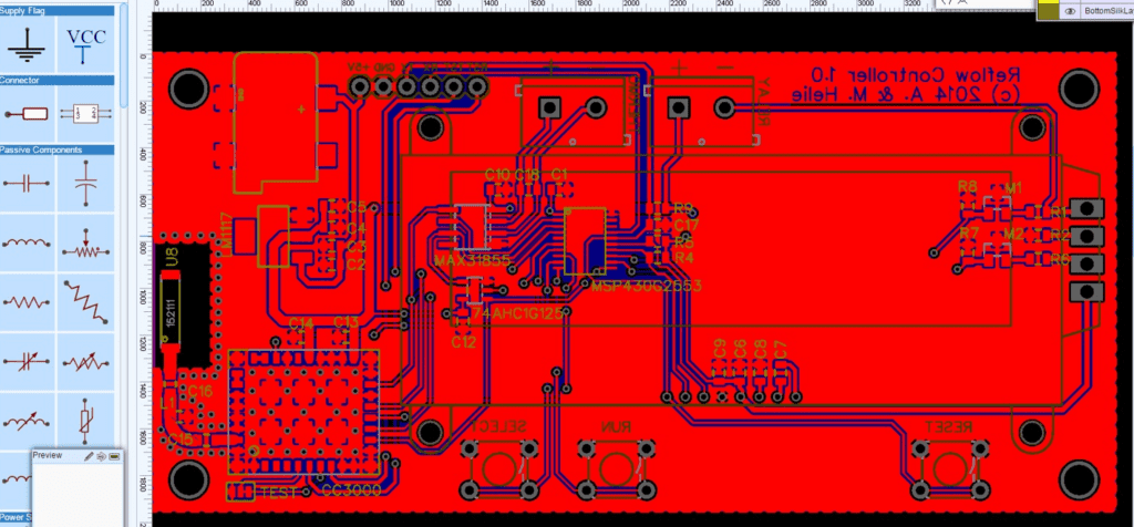
Connect parts. Place all the components properly on one side of a single-layer PCB and establish connections on the other. All the components and tracking should be on both sides of double-layered boards. Colors denote layers on multilayer boards. The bottom layer might be blue while deeper layers have different hues.
White arrows indicate component trace routes, while green lines identify connections. Blue lines indicate rails. Red circles show tracking problems.
Layout Printing
The final process is printing the layout. Do this by going to the file’s output and selecting print. A print layout window for designing a printout will appear.
There are many customizable settings, such as rotation, mode, and more. A drill plot, an illustration, a surface mount technology mask, and a solder resist are the four different modes available. The yellow module may be printed in art mode as well.
If your circuit needs an SMT module, the SMT mode is the way to go. The drill hole size and location may be more precisely defined with the use of the drill plot layer. The layer of solder resistance aids in the avoidance of electrical shorts.
Conclusion
A well-designed printed circuit board (PCB) is the first step in creating a working prototype. For this reason, reliable board template software for creating circuit boards is an absolute necessity. This program is useful for drawing schematics.
