The circuit board manufacturing process needs complex procedures so as to achieve viable products that function correctly. And considering PCBs are the fundamental backbone of almost all electronic components in the market today, manufacturers in the PCB industry try their best not to mess up the PCB production process.
Printed Circuit Boards come in three varieties, single layer, double layer, and multi-layer Printed Circuit Boards. Due to these structural differences, some Printed circuit Boards may need up to twenty steps or more to hit the finished product mark.
The complexity of an actual PCB directly correlates to the number of stages that the PCB has to go through to complete the production phase. Therefore, Printed Circuit Boards bearing more layers than one must go through more production steps than those with only one layer.
Moreover, cutting back or skipping any necessary PCB production steps negatively impacts the circuit board, rendering it useless or substandard which is something that a contract manufacturer and PCB companies don’t like
The Printed Circuit Board Production Process
To ensure you get the production process right, you should ensure your PCB goes through the following stages:
The Designing Phase of Printed Circuit Boards
The PCB designing phase is usually the first phase of a PCB manufacturing process. In this phase, the PCB designers create a blueprint that satisfies the client’s requirements. To achieve this feat, designers primarily utilize software such as Extended Gerber (IX274X).
When the designing phase is complete, the finished PCB design is sent to the Printed Circuit Board fabrication house for the next step.
Upon arrival at the fabrication house, the fabricators must verify that the Printed Circuit Board design surpasses the tolerances levels required for production. When the PCB design passes this test, it can move on to the second production phase.
Engineering Questions and Design Review
In this step, a qualified engineer goes through the PCB design to ensure that it does not bear any flaws. To do so, the engineers must review all the components needed for the design to work. They also have to check the PCB structure in depth.
After gaining clearance from the engineer, the PCB design moves on to the next phase.
Printing Circuit Boards
After passing all the design phases, the PCB is ready for printing. However, unlike the engineering plans, PCB plans cannot be printed on 8.8 x 11 printing paper. Instead, a PCB manufacturer has to utilize a special printer called a plotter.
The plotter generates a PCB “film,” which is typically the PCB’s photo negative.
After printing the bare circuit board film, the PCB manufacturer then punches registration holes on the films, which are utilized for alignment purposes at a later stage.
Printing Interior Copper Layer
After printing the circuit board design onto a laminate component, PCB technicians have to pre-bind copper onto the laminate to help bring out the PCB’s structure. They then etch out additional copper to bring out the PCB blueprint onto the laminate material.
Next, they apply a photosensitive film known as resist onto the laminate panel to aid in the production of a structure that matches that of the PCB blueprint.
After aligning the laminate and the resist, they utilize the premade holes to blast the two with UV light. The UV light goes through the film’s translucent parts, hardening the resist.
They then have to wash the PCB using an alkaline solution to help them remove the excess photoresist. Next, a technician pressure-washes the board to remove any dirt on it and then leave it dry.
If no errors occur at this stage, the production process moves to the next phase.
Etching the Core or Inner layer to remove any Copper
The inner layer(s) or core of the PCB must have all the unwanted copper ejected before proceeding to the next phase of production. To do so, PCB manufacturers utilize a process known as etching.
Etching involves encasing the crucial copper parts on the board and leaving the unwanted exposed copper parts bare. The bare copper parts are then exposed to chemicals that etch out or remove them from the board leaving only the necessary copper parts.
When this step is complete, the PCB manufacturing process moves on to the next stage.
However, if the PCB is a multi-layer PCB, then it has to undergo extra steps to cater to the additional layers. These steps are:
- Inner layer imaging – to produce the inner layer
- Inner layer etching – technicians utilize a copper solvent to etch out exposed copper in the inner layers.
- Resist stripping – involves encasing the copper using a photoresist
- Post etch punch – to add in registration holes
- Inner layer AOI –To examine the inner layer
- Internal layer Oxide – for better bonding and it also acts as an insulating material
- Lay-up – to help bond the layers
- Lamination – to laminate the PCBs
- X-ray alignment – to help cater to the drilling bit
When these steps are over, the multi-layer PCB can now move on to the next phase.
Layer Alignment
In this step, technicians utilize the registration holes to align the outer and inner layers. They do so using a punch machine that drives a pin through the holes lining up the PCB layers.
Automatic Optical Inspection
The automated optical inspection (AOI) step, involves utilizing an optical inspection machine to look for defects in the PCB. If errors are found at this stage, they can be easily fixed.
However, if no defects are found, the PCB manufacturing process moves on to the next stage.
Lamination and adding a Copper Foil to the Circuit Board
The PCB lamination process occurs in two distinct steps on a special press table using unique metal clamps:
- The lay up
- The lamination step
The first step (lay-up) involves stacking the layers together, adding a thin copper foil that contains the boards copper traces on the substrate material and pressing onto them using a machine to merge them, generating a PCB stack.
The second step involves utilizing heated plates to apply pressure and heat onto the PCB stack efficiently. The heat efficiently melts off the epoxy found inside the prepreg and the pressure exerted on the stack helps fuse the copper layers.
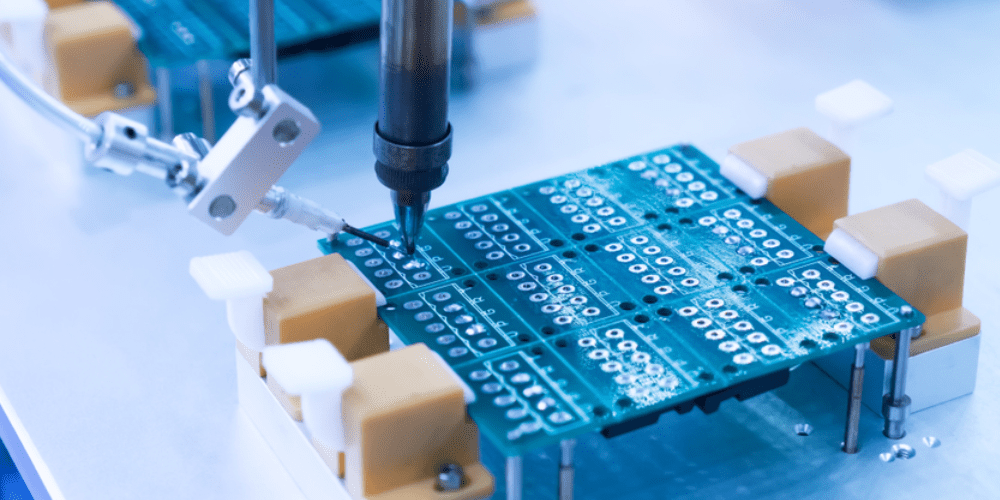
Drilling Circuit Boards
In this step, technicians utilize a special drill (one that is computer-aided) and the PCB’s blueprint to make holes in the PCB.
Two types of vias are generated:
- buried vias
- blind vias
Once the PCB drilling process is complete, any unwanted copper deposition on the board edges are filed off.
PCB Plating
The PCB plating process involves using chemicals to fuse all the layers of the PCB efficiently.
Outer Layer Imaging
In this step, technicians apply a layer of photoresist onto the external layer of the PCB. The process of application is similar to the internal one. However, technicians utilize tin plating for the exterior layer to help shield the copper during outer layer etching.
Etching the Outer Layer
During this procedure, excess copper is ejected from the PCB’s outer layer using the earlier used copper solvent. The tin plating helps shield the copper ensuring that the process is smooth.
External Layer AOI and Application Steps
After undergoing external etching, the PCB then has to go through external layer automated optical inspection to ensure that it meets all the necessary requirements such as hole spacing.
After AOI verification, the PCB then moves on to the application steps:
Solder Mask Application PCB Fabrication Process
In this step, technicians carry out solder mask application to help protect the PCB against corrosion
Silkscreen Application
In this step technicians write crucial data onto the PCB directly. The information might include the PCB’s part number or the company’s ID number. The info comes in handy during assembly for use in consumer electronics.
Finishing the Printed Circuit Board
Finishing up the Printed Circuit Board involves plating the PCB with conductive components such as:
- Hard gold
- Immersion silver
- Lead-free HASL
Once this process is complete, the PCB can now move on to the next stage

Electrical Test, Profiling, Route out, and Quality check
As the name dictates, the electrical test step involves testing the PCB’s electrical reliability. Once you pass this stage, the PCB can then move on to the profiling and route step, where technicians utilize Gerber files to identify the different sizes and shapes of the PCB. Doing so helps sort the PCB much more quickly for packaging.
Finally, the quality check step involves checking the quality of the PCB. Once the PCB passes this step, is ready for PCB assembly.
Conclusion
The PCB manufacturing process is a complex process that requires great care and attention to detail. When carried out correctly, the results are phenomenal, but when poorly done, the results are horrifying. Hence you should try your best to follow the steps in this article to manufacture your PCB.
