LED chaser circuits are popular among hobbyists and electronics enthusiasts due to their visually appealing and dynamic display. These circuits are designed to produce a sequence of flashing LEDs that appear to be moving or chasing each other. A well-designed LED chaser circuit can create stunning visual effects that are perfect for use in various applications, such as decorative lighting, advertising displays, and even in toys.
One of the critical aspects of designing an LED chaser circuit is the PCB layout. The PCB layout plays a crucial role in determining the circuit’s performance, reliability, and overall functionality. A poorly designed PCB layout can lead to various issues, such as signal interference, noise, and even circuit failure. Therefore, it is essential to create a well-designed PCB layout that meets the circuit’s requirements and specifications. In this article, we will discuss the essential aspects of designing a PCB layout for an LED chaser circuit and provide some useful tips and tricks to help you create a reliable and efficient circuit.
Basics of LED Chaser Circuit
Working of LED Chaser Circuit
LED chaser circuit is a simple circuit that can be used to create beautiful lighting effects. The circuit consists of a series of LEDs that turn on and off in a sequence. The LEDs are connected to a microcontroller or a timer IC that controls the sequence of the LEDs. The microcontroller or timer IC sends a signal to each LED to turn on and off in a sequence, creating the chaser effect.
The LED chaser circuit is based on the principle of persistence of vision. When the LEDs turn on and off in a sequence, the human eye perceives it as a continuous motion. The LED chaser circuit can be used for various applications such as decorative lighting, advertising, and entertainment.
Components Required for LED Chaser Circuit
The LED chaser circuit requires a few basic components. The following table lists the components required for the LED chaser circuit:
| Component | Description |
|---|---|
| LEDs | To create the chaser effect |
| Microcontroller or Timer IC | To control the sequence of the LEDs |
| Resistors | To limit the current flowing through the LEDs |
| Capacitors | To filter out noise and stabilize the power supply |
| Diodes | To protect the circuit from reverse voltage |
| Transistors | To switch on and off the LEDs |
The LED chaser circuit can be easily built on a PCB (Printed Circuit Board). The PCB layout should be designed in such a way that it minimizes the noise and interference. The PCB layout should also be designed to accommodate all the components and connections.
In conclusion, the LED chaser circuit is a simple and effective way to create beautiful lighting effects. The circuit requires a few basic components and can be easily built on a PCB. The LED chaser circuit can be used for various applications such as decorative lighting, advertising, and entertainment.
Designing the PCB Layout

When designing a PCB layout for an LED chaser circuit, there are a few important factors to consider. This section will cover the schematic design and PCB design aspects of the process.
Schematic Design
Before starting the PCB layout design, it is essential to have a clear and accurate schematic diagram of the LED chaser circuit. The schematic should include all the necessary components and connections, and it should be easy to read and understand.
When designing the schematic, it is important to keep in mind the physical layout of the final PCB. Grouping related components together and minimizing the length of the traces can help reduce noise and improve the overall performance of the circuit.
PCB Design
Once the schematic is complete, the next step is to design the PCB layout. The PCB layout should be optimized for the specific LED chaser circuit and should take into account factors such as component placement, trace routing, and ground plane design.
When designing the PCB layout, it is important to follow best practices for PCB design. This includes minimizing the length of the traces, using proper trace widths, and ensuring proper spacing between components. Additionally, a ground plane should be included to help reduce noise and improve the overall performance of the circuit.
To help ensure a successful PCB layout, it can be helpful to use PCB design software. This software can assist with component placement, trace routing, and other design aspects, making the process faster and more efficient.
Overall, designing a PCB layout for an LED chaser circuit requires careful consideration of both the schematic design and PCB design aspects of the process. By following best practices and using proper design tools, it is possible to create a high-quality PCB layout that meets the needs of the LED chaser circuit.
PCB Fabrication
When it comes to creating a LED chaser circuit, a printed circuit board (PCB) is an essential component. PCBs are an efficient and reliable way to connect the various components of a circuit. In this section, we will discuss the process of PCB fabrication for a LED chaser circuit.
Preparing the PCB Layout for Fabrication
The first step in PCB fabrication is to create a layout of the circuit on a computer-aided design (CAD) software. This layout will be used to create the PCB. The PCB layout should be designed with the following considerations in mind:
- Component placement: Components should be placed in a logical and organized manner to ensure ease of assembly and maintenance.
- Trace routing: The traces that connect the components should be routed in a way that minimizes interference and ensures proper electrical connections.
- Board size: The PCB should be designed to fit the available space and meet any specific requirements.
Once the PCB layout is complete, it must be exported to a format that can be used by a PCB manufacturer. The most common format is Gerber files, which contain all the necessary information for the manufacturer to create the PCB.
Etching the PCB
After the manufacturer receives the Gerber files, they will use them to create the PCB. The process typically involves printing the layout onto a copper-clad board and etching away the unwanted copper.
To etch the PCB, a chemical solution is applied to the board, which removes the copper that is not covered by the printed layout. The remaining copper forms the traces and pads that connect the components.
Drilling the PCB
Once the PCB has been etched, it must be drilled to create the holes for the components and mounting points. The drilling process is typically done using a computer-controlled drill that ensures accuracy and consistency.
After the PCB has been drilled, it is ready for assembly. The components can be soldered onto the pads, and the circuit can be tested for functionality.
In conclusion, PCB fabrication is a critical step in creating a LED chaser circuit. By following the proper procedures, it is possible to create a reliable and efficient PCB that will provide years of service.
Assembly and Testing

Soldering Components on PCB
Once you have the PCB layout ready, the next step is to solder the components on it. Make sure you have all the necessary components before starting the assembly. You can use a soldering iron and solder wire to solder the components on the PCB.
Start by soldering the resistors, capacitors, and diodes first. Then, solder the IC socket and the LED headers. Finally, solder the power supply terminals and the switch.
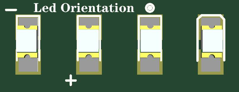
Make sure you follow the polarity markings on the PCB layout while soldering the components. Double-check all the connections to ensure that you have not missed any components or made any wrong connections.
Testing the LED Chaser Circuit
After soldering the components, it’s time to test the LED chaser circuit. Connect the power supply to the circuit and turn on the switch. The LEDs should start blinking in a chaser pattern.
If the LEDs do not light up or blink in the correct pattern, check the connections and the polarity of the components. You can use a multimeter to check the voltage across the components and trace the circuit to identify any issues.
Once you have verified that the LED chaser circuit is working correctly, you can mount it in a suitable enclosure and use it for your projects.
In conclusion, assembling and testing the LED chaser circuit requires careful attention to detail and following the PCB layout and component polarity markings. With proper assembly and testing, you can build a reliable and functional LED chaser circuit for your projects.
