A surface-mount PCB is a circuit board that is created with surface-mount technology. The manufacturing process is a PCB assembly process where electrical component placement is directly on top of the board instead of the components being threaded through. This new method of PCB manufacturing recently took the electrical engineering world by storm.
The two key aspects of SMT, as it is fondly known in the electrical engineering world, are assembly and mounting, and robots or machines do these two major parts. These machines are pre-programmed specifically for the job of mounting components at a highly efficient level.
It may not seem like a lot at first, but arranging electrical components this way goes a long way in reducing manufacturing costs and increasing the speed at which printed circuit board producers can produce PCBs; something that every PCB manufacturer is certainly interested in bearing the amount of competition around in these days.
These machines are referred to in a proper context as surface mount equipment or SMEs. They are of different types and have different functions. They are also quite costly to acquire. This is the reason why some smaller-scale production companies tend to focus on PCB designs and leave large-scale PCB hardware production to larger-scale PCB production services.
Major Equipment Used In SMT PCB Production
The following four pieces of equipment are the major machines used for SMT PCB production. Each machine has a specific function in the production process.
Solder Printer
A solder printing machine is typically used by electronics production companies to print and process screen solder masks, as well as to screen solder paste. These can be done manually. However, It is better to use this machine, because as long as the machines are working at their optimum level, errors can be prevented in the production process.
Pick and Place Machine
Pick-and-place robots do exactly what they are called. Also referred to as SMT component placement systems, these robot takes surface-mount components from a pool and physically add them to the surface of a PCB. Electronic components like capacitors, resistors, and integrated circuits, are usually assembled onto PCBs with this equipment. The microdevices assembled are then used in consumer electronics, as well as for industrial, medical, automotive, military, and telecommunications equipment.
Reflow Oven
This equipment is used for soldering electronic components to printed circuit boards in a process called reflow soldering. Think of reflow ovens as a form of long tunnel for the PCBs that have been already mounted with the right electrical components. The reflow oven has a conveyor belt that moves the PCBs along the tunnel.
They typically have multiple individually heated zones, and every one of these zones has a device that controls temperature. Between the conveyor belt and these controls, a controlled environment is created for the production of PCBs. The temperature control knobs and the speed of the conveyor belts can be adjusted to create various PCB types with different profiles. Not all PCBs, especially those created using surface mount technology, were produced under the same conditions in the reflow oven.
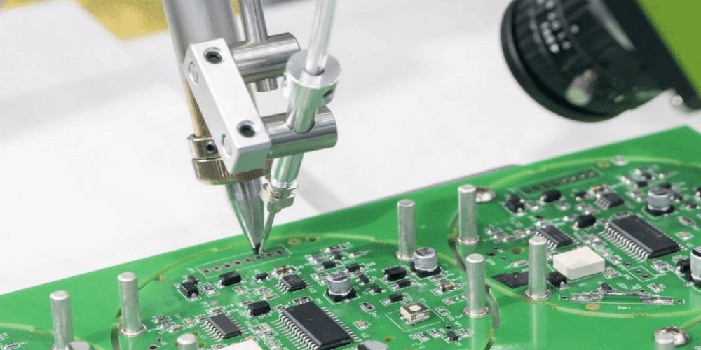
In-circuit Test/Automated Optical Inspection
In this stage of SMT PCB production, a probe is made to test for things like shorts, opens, resistance, capacitance, and other basic variables that show whether the PCB was properly manufactured or not.
In in-circuit testing, something called a bed of nails is used. it is so-called because the device has many pins that are used to contact test points on the PCB.
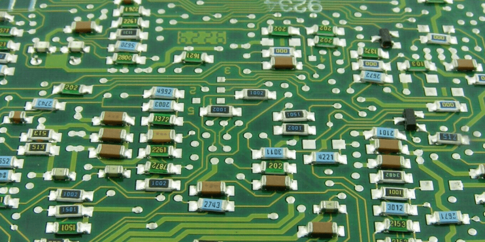
When operating surface mount technology, it is important to know that not all electronic components can be used in SMT PCB production. However, there are a number of components called surface mount devices that can readily be used in SMT PCB production
Passive SMD Components

Resistors and capacitors are the two basic passive SMD components. Occasionally, there may also be coils, crystals, or other parts with specifications. Machines can better grasp where to insert passive SMDs because they come in various fixed package sizes.
Transistors and Diodes
Circuit board elements such as transistors and diodes assist, guide, and regulate electrical flow. Transistors and diodes typically have three connections instead of two, which helps ensure that they can only be mounted in one direction on circuit boards.
Integrated Circuits
Integrated circuits, which are typically (but not always) composed of silicon, are groupings of electronic chips that have been assembled into a single chip. Due to their inherent advantages over other types of circuits, including size, speed, and cost, they are at the core of the majority of printed circuit boards. The last stage of manufacturing is often when manufacturers add integrated circuits.
Differences Between Through Hole and Surface Mount Technology PCB Designs
Through Hole Technology
During through-hole installation, holes are drilled into blank PCB boards, and the leads of each component are inserted into the holes. The component leads are metal connections that stick out from each component which are usually soldered to the circuit board to create a connection. This process is called through-hole mounting.
This was the predominant method of mounting components onto a PCB up until the 1980s when it was anticipated that the through-hole method would be totally phased out.
However, despite suffering a sharp decline in popularity over time, through-hole technology has oddly remained even in the light of SMT, bringing variety and specialization to the table, most notably durability.
The best use for through-hole components is in high reliability which requires a stronger connection between layers. Through-hole components pass through the board. As such, leads to undergo more mechanical stress than SMT components, which are only fastened by solder attachment on the board’s surface.
Because of this, through-hole technology is frequently used for military and aerospace products. These products have a high tendency to be subjected to high temperatures, collisions, and insane speeds. Through-hole technology in the testing of prototypes. This process occasionally needs manual modifications and replacements.
There is a widespread misconception that through-hole assembly has entirely disappeared. Some through-hole components are less costly, and not all components are offered in SMD packaging.
In any case, through hole mounting is regarded as a secondary process in most contemporary manufacturing plants. Axial and radial lead components are the two different categories of through-hole components.

Axial leads pass through a component in a linear fashion, with the lead wire ends exiting on each extremity of the component. After that, both ends are inserted via two different board holes. each of the wire tips of the component goes into a hole on its own. This enables a tighter, flatter fit for the component. On the other hand, because their leads are on one side of the component, radial lead components stick out from the board.
Radial leads are preferable for high-density boards since they take up less space than axial lead components, which are chosen because they fit snugly against the board.
Typically, components with an axial lead configuration include light-emitting diodes, electrolytic capacitors, carbon resistors, and fuses. Ceramic disk capacitors are a kind of radial lead component.
THM PCBs tend to be much stronger than SMT PCBs. This means that THM PCBs can absorb more mechanical stress and they are perfect for components like connectors and transformers that may be subject to mechanical stress.
The disadvantage of this type of circuit board is how it compulsorily must hole drilled into the unmounted board. THM limits the routing space. every hole on the board literally competes for space with electricity routes into the board, especially if the board design is dense.
THM calls for either wave, selective, or manual soldering methods. These are not as stable or as standard as reflow ovens. The surface mount requires attention to one side of the board, whereas through-hole technology often requires soldering on both sides of the board.
Surface Mount Technology
This mounting technique was first known as planar mounting back in 1960 when it was first created, Since then, it has become more common that SMT is now used to create almost all electronics. It is now too essential to PCB design and production, increasing PCB function and value as a whole. This way processing and handling costs are greatly reduced.
The components for this kind of mounting technique are reasonably smaller, and SMT components may be put on both sides of the board.
The surface mount technique has the benefit of allowing for reduced PCB sizes, higher component densities, and more workable space. SMT enables reduced cost and shorter manufacturing time since fewer drilling holes are needed.
SMT components are usually assembled at rates of thousands of placements per hour, as opposed to fewer than a thousand for THM components. With programmable reflow ovens, solder junction creation is substantially more dependable and reproducible than with conventional methods. SMT has been shown to be more reliable and effective under a reasonable amount of shake and vibration.
More than 90% of PCBAs made today use SMT. THM will however be necessary because of unique mechanical, electrical, and thermal factors long into the future.
Surface Mount PCB Assembly Services
There are several surface mounting PCB assembly services available if you need circuit boards built to fulfill certain criteria. The majority of them have a lot of manufacturing process expertise for varying-purpose electronics.
Stages of the SMT PCB Board Design Assembly Process
There are four stages involved in the SMT PCB board design assembly process. These stages are very important and must be carried out appropriately.
Prepare the Initial Circuit Design
The assembler utilizes a solder paste printer to apply solder paste to each circuit board where it is required before attaching components. Solder particles and a unique flux are combined to create solder paste. The electrical connections are formed when this solder paste is heated during the reflow procedure.
Manufacturers typically use stencils and squeegees to verify that solder paste is printed on each circuit board in the appropriate spots. Jet printing is another approach for constructing prototype PCBs.
Placing Surface Mounted Components
After applying and verifying the solder paste, the assembler carefully puts the components on the circuit board. These parts are frequently packaged in trays, reels, or tubes so that they may be extracted by a pick-and-place machine and positioned on the flexible PCB with the use of a vacuum or gripper nozzle.
SMT employs a wide range of parts and connection methods. While integrated circuits exist in a variety of sizes, transistors and diodes are commonly contained in tiny plastic packages. While more complicated circuits may require 200 pins or more, simpler chips may just need 14 pins. For instance, VLSI chips come in rectangular packaging with pins on each of its four sides. Packages for ball grid arrays (BGA) are also extremely popular.
Reflow Soldering
The components are momentarily held in place by the solder paste, but the electrical connections and attachment of the electrical components to the device are not complete until the PCB layout is reflow soldered.
When the solder paste reaches a temperature where solder connections may occur, the components are heated in a reflow oven. This procedure needs to be carefully controlled since the maximum temperature of the components may be close to the temperature required to create dependable solder junctions.
Inspection
Depending on the tools being used and the design specifications, quality assurance inspection might happen at a few crucial points during the SMT process. The solder paste is routinely examined to make sure there are no printing flaws before components are joined. It’s also typical to inspect both before and after reflow soldering.
The processing of PCBs is so complex that PCB-related companies tend to specialize in specific parts of the whole manufacturing process rather than the entire process. Some PCB manufacturers focus on the design process of the PCB only. Some other PCB services focus on the assembly of components and manufacture of the PCB’s final product.
Uses of Printed Circuit Boards With SMT Technology
Light Emitting Diodes
These light-producing devices are used in both public and private spaces frequently. LEDs are also utilized in sectors like the automobile, medical, and computer technology industries. Long life, energy economy, and compact size are three main advantages of LEDs.
As they may assist in transferring heat away from the light source, PCBs are excellent for LEDs. Aluminum is commonly used for PCBs for LEDs because it performs well and reduces the effects of high temperatures on LED burnout. It also enables modest, compact designs by removing the requirement for an additional heat sink.
Industrial Tools
Printed circuit boards and SMT technologies are widely used in the industrial sector. In manufacturing and distribution facilities as well as other types of industrial environments, electronic components are employed to power a large portion of the equipment.
Since PCBs in industrial settings may be exposed to severe temperatures, hard handling, harsh chemicals, or vibrating equipment, they must be especially strong and robust to endure tough situations. They are frequently thicker than standard PCBs and are composed of strong metals that can withstand heat.
Security Equipment
Security systems frequently rely on the utilization of PCBs and SMT technologies, whether they are utilized for residences, governmental structures, or commercial buildings. Beyond what many people are aware of, they have a significant impact on safety and security.
Depending on the specific application, the PCBs used for these goods might vary, but all must be dependable as they must always function properly. Some security systems require an outdoor environment to function, so they must be able to withstand that as well. Modern electronic door locks, security cameras, and even smoke detectors all make use of PCBs.
Aerospace-related Devices
New technology is continuously being introduced into the healthcare field, and PCBs enhance device capabilities. Printed circuit boards are employed in diagnostic, therapy, and monitoring equipment, among other things. Because these PCBs are used to promote patient health, they must be extremely trustworthy.
They must also often fulfill strict sanitary criteria and function best when extremely tiny. Medical imaging systems, infusion pumps, monitoring, and even internal devices are among the equipment that employs PCBs in healthcare.
Medical Equipment
The healthcare industry is continually adopting new technologies, and PCBs provide gadgets with more functionality. In devices for diagnosis, therapy, monitoring, and other purposes, printed circuit boards are employed. Since they are employed to enhance patient health, these PCBs must be incredibly dependable.
They frequently have to adhere to strict sanitary requirements and function best when extremely tiny. Medical imaging systems, infusion pumps, monitors, and even internal devices are a few examples of medical equipment that uses PCBs.
Consumer Electronics
Everyday electronics require PCBs using SMT technology to work. As more electronics become a part of people’s daily lives, PCBs are there to guarantee that they work properly. The boards enable smaller laptops and other devices while still providing a wide range of capabilities. To keep product prices low, most consumer electronics PCBs are quite affordable. However, in order to keep customers delighted, the boards must be dependable.
