LEDs are simple electronic devices that use electricity to produce light. They have two wires, one that connects to the anode (positive) and the other to the cathode (negative). An LED requires two volts and a current of up to 15-20 milliamps to work. There are a variety of different types of LEDs available.
LED PCB
When choosing a PCB for LEDs, you must first know that multiple materials exist. Each material has its benefits and drawbacks. Therefore, you should carefully study the pros and cons of each before deciding on one. You should also seek professional assistance if unsure what kind of LED PCB you need.
LED PCB Assembly
LED PCB Assembly is an intricate process that requires specialized expertise. To get the best results, it’s crucial to have a firm understanding of the process and the components involved. EMSG has been working with LED lights since the beginning, honing our skills in this area.
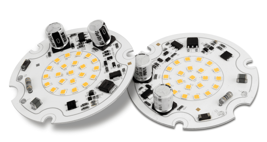
LED PCB is helpful in various applications, from medical equipment to LED lighting. Their high efficiency and long life make them great for these applications. During the assembly process, the PCBs are placed on aluminum sheets, improving the LED’s heat transfer and durability.
The next step in LED PCB assembly is placing components on the board. The process usually involves using high-speed placement machines to place many LED PCB components on the circuit board. This automation allows for a much higher production rate than manual assembly. However, this method can be expensive and requires specialized tools.
PCB assembly requires the careful selection of materials. For instance, a PCB with LEDs must consist of a multilayer FR-4 substrate. In addition, the FR-4 base of the LED PCB needs to have a pattern of closely spaced through vias to conduct heat. These through vias are crucial to getting the LEDs’ power and ground layers.
LED PCB Assembly is a time-consuming process that requires advanced tools. Once you have your LED PCB board, knowing the specific parts to use and where to place them is critical. It’s also important to clearly understand how to assemble LED PCB.
LED PCB Assembly Specifications
In today’s technology-based society, printed circuit boards are everywhere – from cars to computers. Despite their ubiquitousness, not all PCBs have the same manufacturing process. They differ in material and specifications. For example, the base material of a circuit board helpful in LED technology is essential as it determines how well the circuit transfers heat to and from LEDs.
LED PCBs can be single or multi-layers and feature copper or aluminum cores. They can also accommodate Power Converting Electronics. Besides being durable, aluminum can also direct heat away from other components, making them more efficient. As such, aluminum is the most common material helpful for LED PCBs.
The Bill of Materials (BOM) contains information about the components on the board. It also provides the dimensions, width, and routing of the board. It also specifies the voltage, noise, and grounding for the components. Then, it’s time to put the components on the board. This process takes several steps, and a technician must be present at each step to install the components.
LED PCB Assemblies specifications are essential for the longevity of the board. However, a high temperature can damage the components and may result in a short circuit. LED PCBs use aluminum cores to avoid excessive heat buildup and avoid this problem.
LED PCB Assembly Techniques – Manual Plug-Ins Versus Automated Plug-Ins

There are different LED PCB assembly techniques, both manual and automated. While through-hole LED PCB assembly is a proven technique that dates back to the 1940s, there are several advantages to using automated LED PCB assembly. Here are the key differences between the two.
Manual LED PCB assembly involves placing the LED PCB components on the circuit board. With automated LED PCB assembly, the machine performs the soldering and mechanical tightening of the components. This is a time-consuming and labor-intensive process. However, automated PCB assembly makes it possible to produce high volumes of LED PCBs at a meager cost. This technology also allows for automated optical testing, which is impossible with manual LED assembly.
We can perform LED PCB assembly on single or multi-layered boards. Panelboards typically consist of normal FR-4 boards, single or two layers thick. They have aluminum as the core material. Single or multilayer flex PCBs are also available. However, adding multiple layers to the PCB will reduce its flexibility.
Automation increases the consistency of finished products. It reduces the risk of human error. However, manual assembly is still necessary for prototypes and low-volume runs. For example, some surface mount connectors may float up during reflow. Also, manual assembly is often helpful for repairs of an existing PCB.
Learn the Basics of LED PCB Design With Altium Designer
Learn the basics of LED PCB board design with Altium Designer. The tool will help you with component placement, Dielectric constant, and Thermal expansion. You’ll also learn about the Altium Designer’s integrated SPICE simulator. Using this tool, you can simulate the electrical behavior of your LED PCB, including the hot spots that can cause failure. This allows you to make changes without having to redo the entire board.
Circuit design tools in Altium Designer
Altium Designer is a comprehensive PCB design tool integrating all of the design tools you need to design safe LED PCBs. This program uses a rules-driven design engine that helps designers meet industry reliability standards. This allows you to create high-performance circuit boards with low power consumption. It is also incredibly easy to use.
The software suite is available for Windows and starts at around $7000. It includes the hardware gallery for the Raspberry Pi and Arduino development environments and is extensively helpful by leading educational institutions and universities. Despite being relatively expensive, it offers a good led circuit board layout editor and a wide range of improvements.
Another essential feature of Altium Designer is its integrated SPICE simulator. This tool lets you simulate the electrical behavior of an LED PCB. This simulation is crucial in identifying hot spots on a board and enables you to make the appropriate corrections without requiring a complete redesign. Additionally, this software allows you to design higher-power LED systems that require an LLC resonant converter.
Component placement in LED PCBs
Component placement is an essential factor when designing LED PCBs. Because LED components generate extra heat, they need special consideration regarding PCB design. In addition, there should be enough space between the LED pads and traces. If they’re too close together, this can cause issues in manufacturing.
Component placement in LED PCBs is critical to ensure they perform as designed. Components placed at the right distances can prevent overvoltages. In addition, the correct placement of components can help maintain the integrity of the solder joint. Proper placement can significantly affect the product’s quality and reduce production costs.
Proper placement can also ensure that the board fits perfectly. The manufacturing process determines the exact placement of the component. For instance, if we assemble the board with a conveyor belt, the components should be placed away from the edge to avoid damaging the board during manufacturing.
Dielectric constant
The dielectric constant (DK) of PCBs is a vital parameter. Generally, a higher DK increases with frequency, and a lower DK decreases with frequency. However, the dielectric constant for high-frequency substrates is relatively constant. Therefore, high-frequency substrates can have relatively low losses. For example, the dielectric constant of most PCB materials varies from 0.02 for common materials to 0.001 for very low-loss high-end materials.
The dielectric constant measures the electrical charge a dielectric material can absorb in the air or a vacuum. It is an important consideration when designing a circuit with LEDs. The higher the dielectric constant, the more electrically conductive it is, and the lower the dielectric loss.
Thermal expansion
Thermal expansion is an essential consideration in the design of LED PCBs. However, this phenomenon can seriously compromise the performance of a packaged LED device. This problem is severe when we operate the LED at a high current. To avoid this problem, proper thermal management and reliable inspection of the packaging materials are necessary.
A good LED PCB has good thermal conductivity and excellent electrical insulation. It also has good machining and mechanical properties. Usually, it is made of an aluminum core substrate, as it dissipates heat well. Moreover, this type of substrate is suitable for SMD LEDs, which have very high heat output.
Solder mask oil peeling
Solder mask oil peeling is a problem that can affect any LED PCB design. Unfortunately, it is difficult to pinpoint the exact cause of this problem and how to prevent it. However, we can take specific steps to avoid it. The first step is to understand how to identify the problem.
A solder mask is widely helpful on printed circuit boards, and it may not be easy to detect if the mask has failed to adhere properly. However, you can check the solder quality by performing visual inspections with a 1.5 to 10-power magnifier. You can also apply conductive tape to the solder mask for proper adhesion.
There are several solder masks, and dry film solder masks are similar to stickers. First, they are applied to the board and then peeled off. Another method is to use liquid solder masks, which follow the same process as dry film. The only difference is that the dry film solder mask has more stringent curing conditions. As a result, it tends to be brittle and can crack when exposed to high temperatures.
Problems And Solutions Often Encountered In LED PCB Assembly
Led PCB assembly is a complex process that requires the correct care and attention to detail. Many challenges come with LED PCB assembly, from design flaws to material selection and dimensions. Proper assembly is vital to LED’s functioning, as improper connections can cause short circuits.
Design flaws
LED PCB assembly involves a variety of processes. It starts with the design phase and continues through the manufacturing and assembling phases. The design phase always starts with a layout showing how we should arrange the LEDs. The layout also includes the wiring arrangements. The layout should label the different components, so the consumer will clearly understand the progress.
We can inspect LED PCBs using different techniques. One of the most common inspection methods is a visual inspection. This method is the fastest and easiest way to identify errors. It also allows you to test several samples in a short period. Visual inspection is also helpful for checking the shape and size of PCBs and can determine whether solder overlaps are even. This method also allows you to check plating quality and surface smoothness.
Design flaws often affect the quality of finished products. While the design process and PCB manufacturing are complex, many common issues can affect the final product. Some of these issues are caused by human error, while others result from poor manufacturing practices.
Material selection
One of the significant challenges encountered during LED PCB assembly is the selection of the appropriate materials. Choosing readily and locally available materials are critical. Otherwise, consumers may lose confidence in led circuit board products. Moreover, choosing durable components will reduce the costs of design revisions. This will also help select the right BOM for the LED PCB assembly.
When choosing the appropriate materials for PCBs, consider the intended application and environment. Also, consider whether the final product needs to meet industry or regulatory standards. By doing so, you will be able to ensure that the final product will meet the necessary safety specifications. For example, choose a material with low lead content if there are risks of electrochemical migration. In addition, a low tin content can control the emergence of conductive filaments, which is essential in high-stress environments.
When choosing a PCB material, you must consider the size of the board and the current it can carry. If the current drawn by the circuit is high, you should choose a metal-core PCB. These PCBs have excellent insulation and thermal transfer properties. Metal-core PCB boards are also helpful in high-power LED applications. As LED devices continue to grow in popularity, led circuit board manufacturing is moving toward smaller, more densely-packed boards. This is also driving the development of 3D plastic PCBs, 3D molded plastic boards, and increased use of IC chips.
Dimensions
LED PCBs are widely helpful in medical tools due to their high visibility. They integrate into small torches that help general practitioners illuminate tiny body parts and are also beneficial in internal diagnostic instruments. They are also helpful in providing LED lighting for operating tables.
LED PCB assemblies must conform to many specifications, which can be quite complex. Therefore, the first step to improving heat management on LED PCBs is smart design and precision prototyping. When using more complicated and densely packed circuits, it may be necessary to use metallic board substrates or other additional components.
Another consideration is the depth of led circuit board holes. Normally, these holes are non-penetrating, so they must be at least 0.05mm in depth. However, it is essential to note that the depth should not be smaller than the board thickness minus 0.5mm.
LED PCBs With SMD LEDs
LED PCBs with SMD LEDs offer many benefits over traditional light bulbs, including reduced size, less circuitry, and lower power consumption. In addition, this technology eliminates the need for large, raised circuitry that increases the heat produced by LEDs. LED PCBs that use SMD LEDs also feature reduced weight, which enables them to be helpful in thin, lightweight devices.
LEDs come in two different sizes, SMD 2835 and SMD 3014. SMD 2835 LEDs are the most popular because of their long life, low power consumption, and many available colors. They can also vary in white depending on the bin color of a given led circuit board manufacturer. SMD LEDs are also polarized, with each LED module having a different polarity. This ensures that the LEDs remain safe in their operating voltage and avoid excessive overheating.
Surface mount devices require no soldering and are also less expensive. They are mounted using a microscope and component lifting machines. This method of LED PCB assembly is faster than through-hole PCB assembly, but it is unreliable in mechanical stress and can be expensive. In addition, LED PCB assembly requires careful consideration of the components and adhering to various specifications.
SMD LEDs use a supporting block with a conducting layer. This conductor connects the LED chip to the circuit board. It also provides electrostatic discharge protection and controls the brightness of the LEDs. It also allows for using a wide range of small surface-mount LEDs.
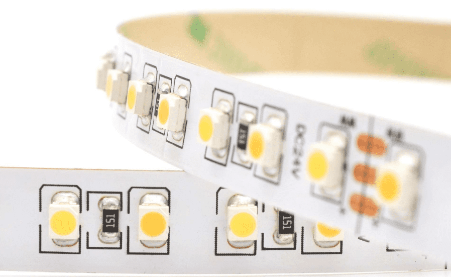
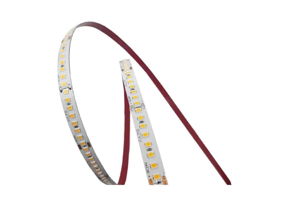
Single Point Surface Mount And Integrated LEDs
Single Point Surface Mount and Integrated LEDs are types of light-emitting diodes. The former is mounted on a led circuit board, while the latter integrates into LED light strips. They are packaged in plastic casings and contain a phosphor. The LED chip produces blue light, and the phosphor material translates it into green and red wavelengths. Single Point Surface Mount and Integrated LEDs have similar characteristics but differ in their packaging.
Different chips can individually control Single-Point Surface Mount and Integrated LEDs. In addition, a chip can control multiple LEDs chained together. Examples of such chips are the APA102 and UCS1903. A chip may also control individual LED colors. Some of these LEDs contain an internal resistor to limit the current.
The power limit of an LED depends on its current and voltage ratings. Generally, a single LED needs only a few milliwatts of power. However, the CREE LED is particularly bright and can dissipate over one Watt of power.
LED strips can also be SMD or COB. The process involves placing a silicon wafer on a substrate and then heat-treating it.
Application of LED PCB Assembly
In assembling led circuit boards, the bill of materials is crucial data. It lists all materials needed to build the printed circuit board. We generate the bill of materials by the LED circuit board software integrated with the CAD system. The software keeps all the parts in a CAD library and can help produce the bill of materials.
Aluminum
Aluminum is a common material helpful in LED PCB assembly service because of its ability to withstand higher currents. Compared to FR-4, aluminum can withstand higher currents without damage. However, the flexibility of the aluminum LED Circuit Board may not be the same as the one produced with FR-4.
LEDs generate massive amounts of heat, which is not ideal for a board. A heatsink is an obvious solution, but the LEDs are too small to allow for this solution. In addition, heatsinks block light, reducing the effect of LED lights. Aluminum PCBs are a better choice for these LED lighting applications because they dissipate heat better.
Polyimide resin
Polyimide PCB assembly is a process that utilizes flexible material to cover exposed circuitry and resists heat. It is an excellent choice for this purpose because of its high flexibility. The material is typically thin, with a polymer layer thickness of 50 microns and a copper layer of 18 microns. The overall Printed Circuit Board thickness is about 0.2 millimeters. Its flexibility and robustness largely determine the advantages of polyimide. This material is also helpful in rigid-flex PCBs, a popular choice for high-tech electronic applications.
Polyimide is extremely thermally stable and can withstand temperature changes up to 260 degrees Celsius. Additionally, it has high thermal conductivity and is resistant to heat during manufacturing. Additionally, polyimide PCBs retain their shape even under extreme temperatures.
Ceramic fillers
Ceramic fillers are helpful in LED PCB assembly because they increase flexibility and minimize the need for cables and connectors. They also improve the insulation properties of the board. These materials are also flexible and can bend without damaging them. But they are not designed to flex continuously. In some cases, they may bend in a few seconds.
Ceramic substrates have excellent electrical and thermal properties. They can withstand high temperatures. LED lights are also chemically stable, allowing them to be helpful for long-term immersion in corrosive environments. They have many advantages and will gain more applications as the market grows.
Printed circuit board
LED printed circuit boards are highly flexible and customizable. LED PCB manufacturers can manufacture custom LED circuit boards by buying components from other manufacturers and reselling them. However, this can be an expensive and time-consuming process. When selecting a manufacturer, visit the manufacturer’s offices or use a prototype to evaluate the quality of the products. Also, when choosing design software, ensure it is suitable for LED Printed Circuit Board manufacturing.
As with any LED circuit board, LED printed circuit boards are susceptible to defects. These defects can lead to the malfunctioning of the final product. Therefore, LED PCB assembly must adhere to strict standards to minimize the impact of defects.
Medical devices
LED PCB assembly for medical devices is a fast-growing industry. LEDs can significantly reduce the cost of producing medical devices. Medical devices are often highly specialized and require high reliability and accuracy. Medical PCBs need to meet stringent standards and have extensive documentation. They must be monitored and evaluated throughout the manufacturing process. Different regulatory bodies have developed standardized rules for medical device PCB assembly. These organizations include the Association Connecting the Electronics Industry (ACEI), the International Organization for Standardization (ISO), and the U.S Food and Drug Administration.
Medical LED PCB assembly requires precision and high accuracy. In addition, because LEDs are flush with the surface, they require less power than other PCBs. They also need minimal space and are highly resistant to vibration and constant motion.
Welding LED PCB board Components
Welding LED PCB components is a process that involves applying heat to a surface to form a connection. The application of heat produces a change in the CTE of the material, and this change will be permanent. In general, it is best to keep the CTE of the substrate as low as possible. The optimum temperature for soldering LED PCB components is 250degC.
How to Reduce LED PCB Temperature
A common problem associated with LEDs is their high temperature. High temperatures can result in failures due to thermally induced stresses. Also, LED packages and PCBs have different thermal expansion coefficients, which can lead to a temperature imbalance. Fortunately, there are several ways to mitigate the temperature problem.
One method is to increase the thermal conductivity of the LED PCB. We can do this by lowering the thermal resistance between the board and the LED source. Thermal resistance over the interface should be less than 0.2 K/W. Anodizing and etching can reduce thermal resistance. Using thermal glue or sticky tape is also an option.
Another way to reduce LED PCB temperature is to reduce the spacing between the LEDs on the PCB. The wider spacing between the LEDs increases their thermal power and, therefore, the temperature of the Printed Circuit Board. The manufacturer of LEDs usually specifies the recommended spacing between the chips, and you can follow this spacing to minimize the temperature increase.
Another way to reduce LED PCB temperature is using metal-core PCBs (MCPCBs). MCPCBs are a kind of Printed Circuit Board that incorporates a base metal material as a heat spreader. Most commonly, aluminum is helpful for this purpose. MCPCBs also have a layer of thermally conductive dielectric material, which helps to dissipate heat from the LEDs.
